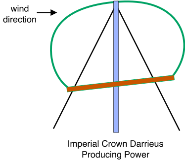
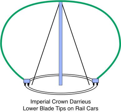
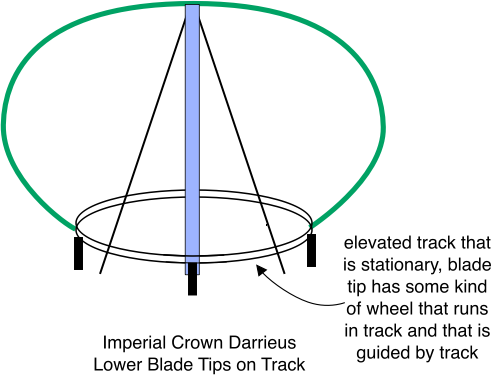
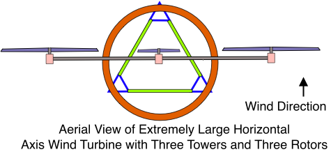
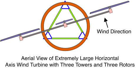
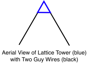
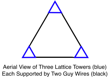
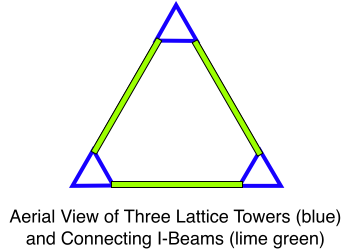
No, 20 MW is not a typo… this post describes a Darrieus Wind Turbine configuration that to me seems almost infinitely scalable. I chose 20 MW out of a hat because I felt it’s a good jazzy way to communicate the immensely scalable nature of this machine.
Actually, this post describes two interesting ideas – a concept for designing a highly Scalable Darrieus Wind Turbine, and a direct drive concept for eliminating the turbine’s gearbox. And by the way, the direct drive concept will work on horizontal axis wind machines as well.
I’m not a mechanical engineer, so many of the diagrams presented here are purposely naive. I’m taking this approach because I feel that the most important objective of this blog post is to communicate the significant and novel aspects of these two ideas – the scalable turbine and its direct drive system. If these ideas prove viable, I hope that some talented scientists and engineers will find the right mechanisms, configurations, and designs for reliably implementing these concepts.
The Scalable Darrieus Wind Turbine
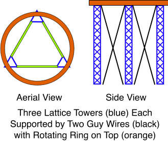
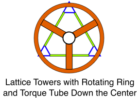
The basic idea is to provide an improved and more scalable means for guiding and stabilizing the airfoils of a vertical axis wind turbine, and also for carrying the airfoil loads. This is accomplished with a stationary circular track that is suspended in mid-air. The track is supported by a number of towers arranged in a circular fashion. The following diagram illustrates these features. (In the interest of clarity, the diagram has quite a few simplifications. For example, only two towers are depicted. An actual machine would have at least three towers. A large diameter machine will have as many towers as are necessary for supporting the track and its loads. Furthermore, only two circular tracks are shown. A very tall machine will have as many circular tracks as are required to stabilize and support the airfoils, and to support the direct drive generators that I will describe momentarily.)

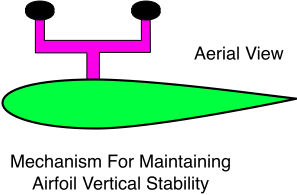
Here are two of the naive diagrams I promised you earlier. These diagrams describe the general idea for implementing the interface between the airfoils and the suspended circular track. First, an aerial view:
And here’s a side view:
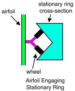
The circular track cross-section doesn’t look very streamlined, does it? No matter… we can easily come up with a shape that minimizes the turbulence generated by the track. The structure that supports the wheels (colored purple in the diagrams above) will also be streamlined, and the shape of the circular track will be modified in order to shield, to the greatest extent possible, the wheel supporting structure from contact with the wind that flows through the rotor. It is also very important to notice that the negative aerodynamic characteristics of the track, the towers, and any auxiliary devices that are attached to the airfoils (like the wheels and their supporting structure) are nothing to be concerned about. This is so because it is easy to “drown out” these negative effects with scale. For example, adding more towers certainly increases the turbulence in the wind flowing through the rotor, but this isn’t a problem because each tower added permits the scale to be increased by a very large fraction. Thus, the added energy capture from the increase in scale more than makes up for the increase in aerodynamic interference.
If you’re like me, you just don’t feel right sticking auxiliary mechanical devices on the high speed part of an airfoil. Here’s a couple of alternative implementations that get around this problem. Neither of these implementations would contribute significant aerodynamic drag, though mechanical friction would still be present. These implementations employ a great many wheels that are attached to the circular track, and that engage the airfoil one after another as it makes its way around the track:
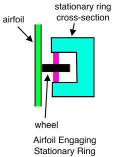
Here’s a modification of the apparatus above that minimizes airfoil bouncing:
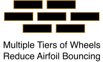
And here’s the second alternative:
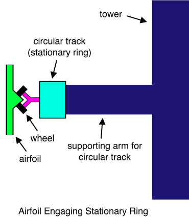
One of the problems that the wind industry is currently struggling with is the growing size and weight of wind turbine components. In some cases the components grow to a size that can’t be transported to the wind farm construction site. In other cases the components are so heavy, and are suspended at such great height, there are no cranes available that can handle the job. For these reasons, I’m thinking that a very large Scalable Darrieus Turbine may have a number of smaller, light-weight blades. Selecting a multiplicity of small airfoils instead of two or three big ones also makes for a quiet machine, not to mention a safer one. And more airfoils reduce the fluctuations in thrust and output power that so notoriously plagued the traditional two-bladed Darrieus. If a multiplicity of smaller airfoils is selected, perhaps the blades could be assembled from sections at the wind farm construction site:

I once had a Bergey 10 kW blade. It was fascinating. It was made with a low cost fiberglass extrusion process. It was very strong, yet flexible. I’m wondering if a very long blade could be manufactured by connecting many of these sections end to end.
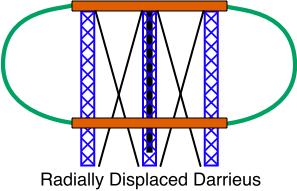
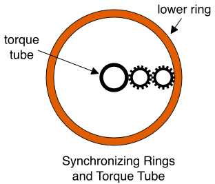
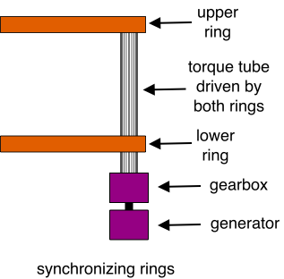
It may be necessary to provide the Scalable Darrieus with a means for neutralizing the tendency of the blades to outrun or lag behind one another. There are many ways of doing this, and I don’t think it will be very difficult to implement this functionality. One method would employ a giant small diameter circular tube that is very light in weight. This tube would connect the wheel supporting structure of the airfoils one to another. Here’s the general idea:
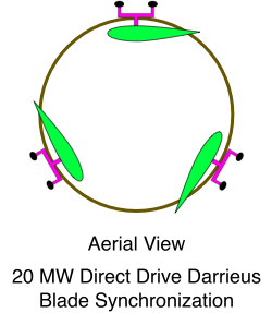
Though not shown in the diagram, the synchronizing ring would rotate inside of the circular track. In this case, the circular track acts as an aerodynamic shroud that shields the rotating ring from contact with the wind that flows through the rotor. This minimizes drag, and it minimizes the turbulence generated by the ring.
An alternative way to synchronize the blades replaces the circular tube with a cable. This cable is also shrouded by the blade guiding track. I don’t have time to explain it right now, but I’ll add this and more to this blog post in a few days. (And in addition to the cable, there are still other alternatives for synchronizing the blades.)
Variations on the Scalable Darrieus Theme
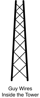
I don’t even know where to start. I’ll bet you’ve already thought of a few variations of your own. Let’s refer back to the first diagram that shows the whole machine. The towers can be placed inside of the circular track instead of outside. The towers may be supported by guy wires that all attach to the ground at some favorable location that is also inside of the circular track. In this case, the rotor blades run outside the circular track rather than inside. Only the upper ends of the airfoils are joined together in this variation. The lower ends extend toward the ground beneath the lowest circular track, and are not attached to anything.
Speaking of joining the ends of the airfoils, consider the possibilities that become available if all of the ends of the airfoils are uattached:

Now the rotor blades are not constrained to circular motion. Suppose there’s a site with predictable winds:
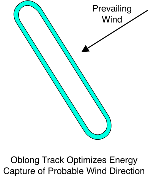
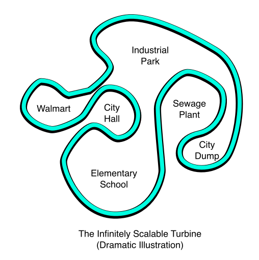
Even at sites where the wind direction isn’t predictable, there may be other reasons for choosing a path that isn’t circular. In this case, given unpredictable wind direction, the path would be designed so that the blades travel an equal distance in every possible direction. You could route the blades past some kind of obstruction… heck, let ’em meander through town to showcase the mayor’s commitment to renewable energy. Shoot ’em through the elementary school and let each kid have a blade of her own. When the wind isn’t blowing she can give her blade a name and then fingerpaint it. Run ’em by the Lion’s club for a fundraiser auction where ordinary citizens can bid on a blade for the environment. The winner gets his name on a little gold plaque stuck to the blade like they do with bricks. Investors will readily agree that a Hundred Mile Per Hour Symmetrical Darrieus Airfoil has a way more pizzazz than some stupid brick. I bet they’ll be pushing and shoving, necks craning to see the auctioneer up on the stage. This thing could turn into a veritable bonanza for environmental awareness, not to mention funding the diversification of the nation’s energy portfolio.
Okay, let’s put the crowds of wildly cheering treehugger groupies aside for a moment and return to the issue of scalability. Now tell the truth – when you read the very first sentence of this blog post, did you roll your eyes when I called this machine “almost infinitely scalable”. You did? Well… did I lie? Yes, I guess I did lie… for now you know the astonishing truth –
The turbine proposed here is infinitely scalable.
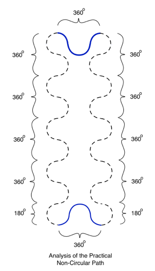
The non-circular path is interesting, but is it practical? Absolutely! It’s easy to construct a non-circular path that is very practical. All you have to do is connect a bunch of 180 degree arcs of alternating polarity, and throw in a few 45 degree arcs to make it work:
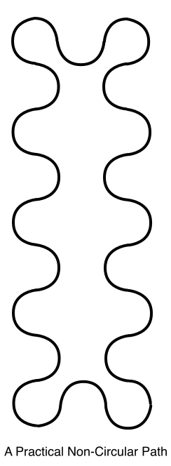
Huh!? What’s so great about this!? Here’s a diagram that shows why this path is practical:
If the path of the Scalable Darrieus is circular, and if the circle has a very large diameter, then blades will be moving nearly directly into the wind and directly out of the wind for a long time before they reach the power producing part of the arc. This may present a problem if certain combinations of ideas from the Salient White Elephant blog are selected. But in this case the problem can easily be remedied with the 180 degree arc segment idea:
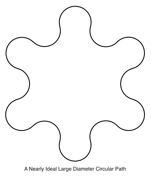
If blades drive magnets in a direct drive implementation, then there is another way to improve the performance of a large diameter circular track – turn off all of the coils that are on those portions of the track that are nearly parallel to current wind direction.
Before leaving the subject of the path taken by rotor blades, I want to raise an interesting question. Obviously, the designer will select the smallest number of towers that are possible with the given type of turbine. With this in mind, imagine the blades follow a square path (requiring 4 towers). Now if the wind blows directly along two sides of the square, then the blades are producing nothing but drag for 50% of their cycle. If an oblong path is selected (requiring two towers, one at each end), then the wind might blow down the long dimension of the oblong path, which means the blades will produce nothing but drag for virtually 100% of their cycle. But if we select a triangular path, the worst case has the wind blowing directly down one side of the triangle, which has the blades producing nothing but drag only 33% of their cycle. So 4 towers = 50%, 3 towers = 33%, 2 towers = 100%. What does this strange sequence mean? I don’t know!
It would seem there are many applications for these somewhat arbitrary paths that are like a “wind turbine fence”. Imagine, for example, putting one of these fences on top of a building. As I drive around the city of Ottawa, I see a great many buildings that could support a “turbine fence” of sizable output. And it doesn’t seem the machine would be in the way of anything, or be dangerous in any way.
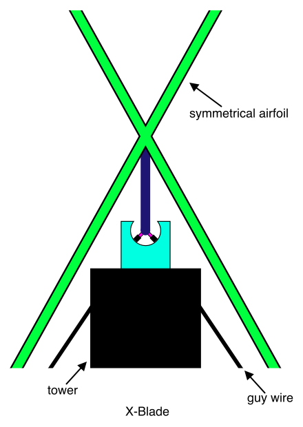
Here’s a guyed variation that has the blade follow a large circular or oblong path, or the ” nearly ideal large diameter circular path” just described:
As you read on, you may be shocked at the bizarre variations that are possible with the Scalable Darrieus concept. Your first impression may be that these ideas are interesting, but not very practical. I urge you not to dismiss this post too quickly – first impressions can be misleading. But here I’d like to say that there are so many compelling variations of the Scalable Darrieus concept, I find it difficult to adequately address details like blade synchronization without turning this post into a 500 page novel. With this in mind, I’d like you to question whether the airfoils need to be absolutely synchronized. Is there any other way? Well, I can think of two other possibilities. The first is to devise a means for preventing the airfoils from getting closer than, what… 20 feet of each other? Having prevented the airfoils from getting too close, they are left to make their way around the track on any schedule that suits them. (Balancing mass about a rotational axis is not an issue when the radius is very large.) The second synchronization concept synchronizes groups of airfoils, and then prevents the groups from getting too close to one another. In this embodiment, groups of (say) six airfoils move at the same velocity, but the velocities of the groups can differ.
Another issue I haven’t addressed is how to start the machine. I hope to have more time to fill in the details later.
Well why stop at airfoil auctions and arbitrary paths!? We’re on a roll now folks, so let’s put the pedal to the metal and blow this popstand wide open! At sites where the wind has one predictable behavior during one season, and different predictable behavior in another, simply build two tracks and then switch the blades with the changing seasons. And if it has one behavior in the morning and another in the afternoon, throw a switch and direct the blades down the alternate track. If it’s hard to believe this will work, remember that 500 ton freight trains pulling 70 cars are switched from one track to another in exactly this manner every single day!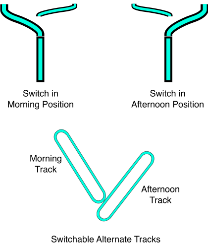
Here’s another idea for optimizing the path based on current wind direction:
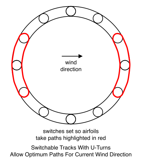
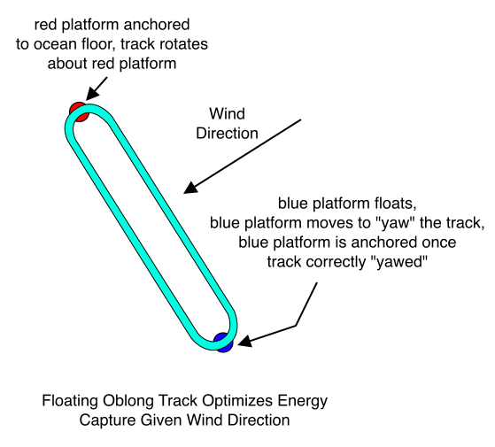
Or what about an offshore variation in which a floating oblong track is yawed so that its longer dimension is at a right angle to the approaching wind:
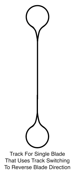
If only a single blade is used, then the long dimension of the oblong track can be used for both blade directions. When the blade approaches the somewhat circular end of the track that turns the blade around, a switch routes it to one side of the fork. This switch toggles its polarity as the blade goes round the nearly circular end, thus routing the blade back down the long straight part of the track.
And given we can switch between tracks, why not have a short detour track with an automatic blade washer on it? An airfoil is diverted to the blade washer once every other day or something like that.
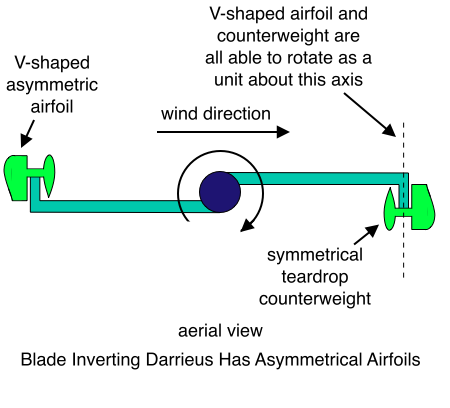
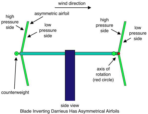
We can add another short detour that inverts the blades. This allows us to leverage the superior aerodynamic performance of asymmetrical airfoils:
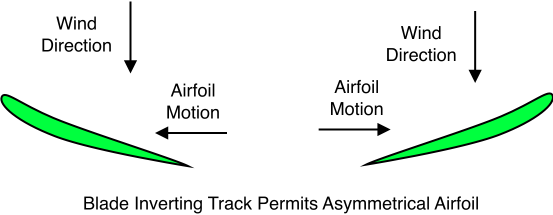
And the blade inverting track:
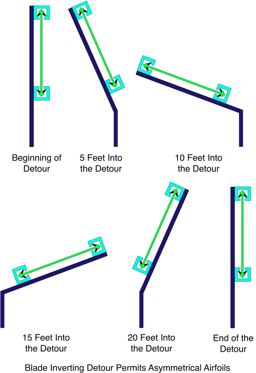
But what if we want to invert the blades at a location that changes from one hour to the next? There’s a technique for doing this too! In fact, this technique is so cool that I decided it deserves a post of its own. That post describes how the technique would be applied to the traditional Darrieus design, but it will work just as well on the infinitely scalable turbine. Here’s a link to the airfoil inverting post.
Cable Driving Variation
In order to understand this version, you really should read the the airfoil inverting post first.
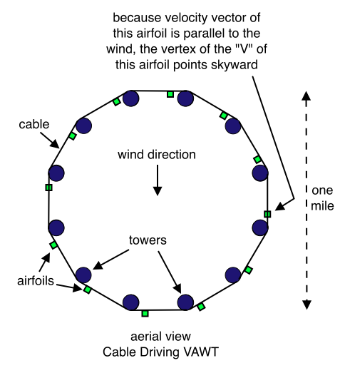
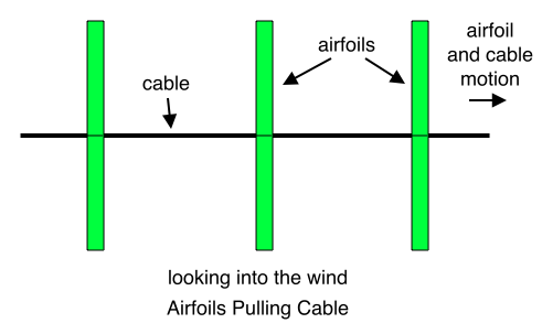
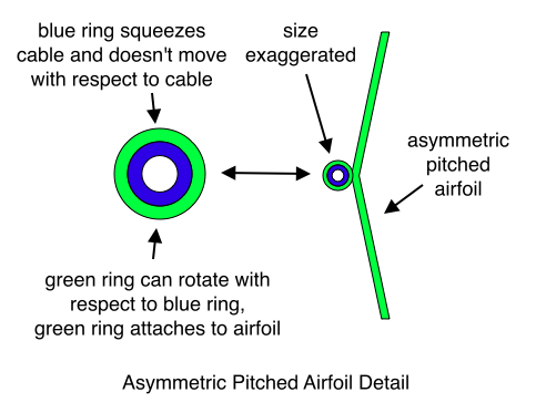
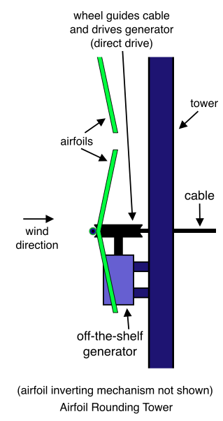
Now I will describe the airfoil inverting mechanism that allows the airfoil to go round the tower. Imagine the airfoil in the last diagram above is approaching the tower. A helical guide inverts the airfoil. The helix starts at 12 o’clock. As we move closer to the tower, the helix rotates in the clockwise direction until it reaches 6 o’clock. The top blade of the airfoil in the above diagram makes contact with the helix at approximately 12 o’clock. As the blade moves closer to the tower, the helix pushes it in the clockwise direction until it has been inverted. After it has been inverted, it reaches the wheel and rounds the tower. If the wind were blowing in the opposite direction, the airfoil would already have the correct polarity for rounding the tower. In this case it will not make contact with the helix. If the wind direction is parallel to the cable, the vertex of the “V” of the airfoil will be pointing skyward. In this case it will not make contact with the helix until approximately 3 o’clock, whereupon it will be rotated 90 degrees in the clockwise direction, and then it will round the tower.
Here’s an alternative approach that does not require the airfoil to be inverted as it goes around the tower. In this approach, the rims of the wheel that drives the generator (i.e. the two parts with the largest radius) are padded with hard rubber or something like that. If the airfoil has the polarity shown in the diagram below, then the low pressure side of the airfoil just rides on those padded rims at it turns the corner.
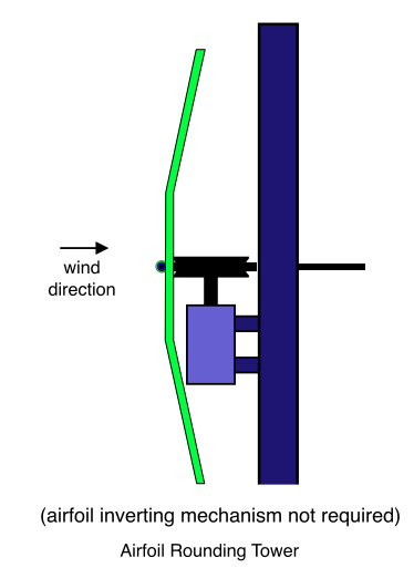
This approach still requires a way to insure that the airfoil is in its “power producing orientation”, though it doesn’t matter which polarity it has. If not in its power producing orientation (as in traveling directly into or out of the wind), then it must rotated 90 degrees before it reaches the wheel.
Note that the airfoils in this machine travel at what we normally think of as “tip speed”. Since this velocity is very high, the drive system depicted above is a direct drive system that does not require gearboxes.
Yet another variation looks a lot like the one just described, except the cable doesn’t move. In this variation, the airfoils slide along the cable. An interesting aspect of this approach, as well as the one just described, is that the cable doesn’t necessarily have to be all that tight. If it sags a little bit, the airfoils will hoist it up somewhat as they make their way between the towers. As for how the airfoils in the stationary cable embodiment drive the generators, perhaps one of the direct drive systems described in the next section of this post could be employed.
Before leaving the discussion of the approach wherein the airfoils are suspended on cables, I’d like to make a point about the nature of the technology described in this post. Suppose you are a scientist with a Cray Supercomputer. Though your supercomputer is mighty impressive, you’re wondering how to build an even bigger one. What would you think of the possibility that a bunch of cheap desktops in houses and buildings around the globe could be connected with a network and rival the computational firepower of your Cray machine? If gearboxes, rotors, and generators are getting to be so large and heavy that we can’t find a crane to lift them, why not consider an approach that is more distributed in some way? I have described the turbine of this post as “infinitely scalable”. I almost feel that I have “cheated” in order to realize this goal, much in the way the Cray Supercomputer guy might say “hey, you didn’t tell me I could use more than one computer in my design – that’s cheating!”. And yet if it’s possible to build a large wind machine with a lot of off-the-shelf directly driven 100 kW generators, then at least we won’t have any trouble hoisting them up onto the towers!
Direct Drive Concept
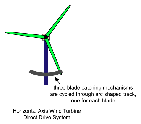
For many years, I tried to dream up a way to use the high speed tips of a horizontal axis wind machine’s rotor blades to directly participate in the process of generating electricity. Perhaps magnets would be embedded in the blade tips, and the coils would be arranged so that the blade magnets passed close by. This would truly be a “direct drive” machine. I’m not sure if the idea I am proposing here should be called “direct drive”, “semi-direct drive”, “almost and for all practical purposes direct drive”, or what. I won’t address the philosophical question of terminology here. The aim is to capture the benefits, or at least most of the benefits, of a direct drive design. I’m not sure whether I’ve achieved this; read on and you be the judge. Recently, I realized that instead of trying to find a way for the rotor blades to directly participate in the process of generating electricity, maybe I could devise a means for transferring the tremendous mechanical velocity of the blade tips to an auxiliary mechanism. This auxiliary mechanism would in turn drive the generator rotor. This is a fascinating approach, as it seems to suggest the use of off-the-shelf generators! Fantastic! In fact, it even seems to suggest the use of multiple smaller generators working in tandem. Even better!
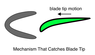
Okay mechanical engineers… prepare yourselves… this diagram is hyper-naive:
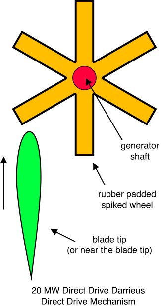
This drive mechanism will require a flywheel of sizable mass on the generator shaft. (Alternatively, maybe the power electronics could be designed to maintain a relatively constant generator rpm so that the blade will not collide with the spiked wheel with excessive mechanical shock.) This approach will also require an appropriately positioned wheel or roller that avoids the situation depicted above wherein the rotor blade rubs along one of the spikes in its longitudinal direction. Again, the diagram is purposefully naive, since I know a real mechanical engineer will have much better ideas for going about this than I do.
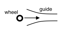
Another approach would act like a baseball pitching machine in reverse. If you’ve never seen a pitching machine, it’s actually pretty simple. Two inflatable tires, each about one foot in diameter, rotate in opposite directions. They rotate in the same plane, and that plane is parallel to the ground. The distance between the tires is maybe a half an inch shorter than the diameter of a baseball. The coach drops a baseball onto a downward sloping track, and the force of gravity causes it to roll into the space between the tires. The tires then “grab” the baseball, and it shoots out of the machine at high velocity. Here’s a drive that employs this idea in reverse:
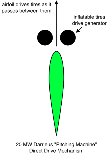
Here’s an implementation for a horizontal axis machine:
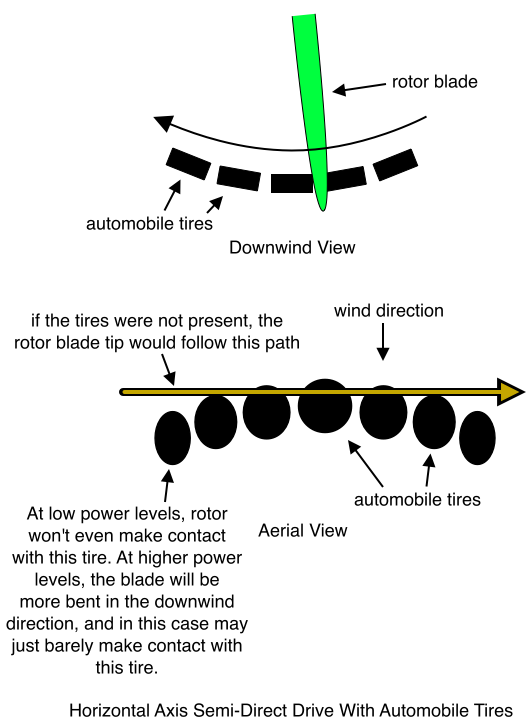
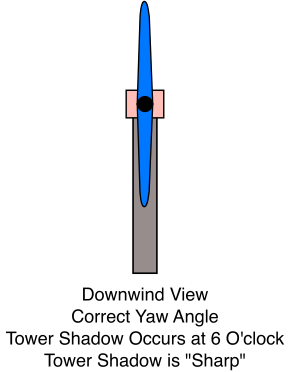
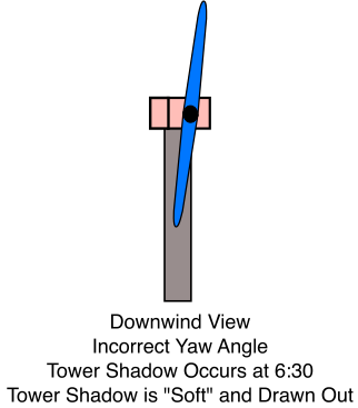
The diagrams above have quite a few tires in order to clearly illustrate the geometry. I’m not sure this many tires would be required, and I’m not sure they’d have to be as large as automobile tires. The idea is to use as few tires as possible, and to cluster the tires as much as possible near the rotor blades’ 6 o’clock position. This is desirable because the 6 o’clock position is the worst of all positions for producing power since it is compromised by tower shadow. As the blade approaches the 6 o’clock position, it may pass some of the tires without making contact with them, but it gets closer and closer to each subsequent tire. Finally, it just barely makes contact with one of the tires, and subsequent tires push it more and more in the upwind direction. After the blade has been maximally displaced from its natural path, the tires begin to be located further and further in the downwind direction. This allows the blade to gradually return to its unimpeded trajectory. (For the sake of explanation, I have talked as though many tires are involved. In reality, the fewer tires the better.)
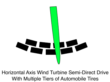
The tires are, of course, either coaxial with multiple generators, or else they’re all mechanically connected and drive a single generator. Will the rotor blades skid across the tires the way a car with locked wheels skids across pavement? I don’t know, but remember that one advantage of this approach is that, given power, torque and speed are inversely related. So high speed means low torque! Another point to be made here is that bouncing of the rotor blade may be minimized by providing multiple levels of tires, each with a small angular phase shift relative to its upstairs and downstairs neighbors:
Yet another variation attempts to minimize the aerodynamic interference of the tires by stacking them all in a single vertical column that is centered about the rotor blades’ 6 o’clock position. In this case, each tire rotates at a different rpm, and therefore drives a separate generator. (Alternatively, all tires can drive a single generator if each tire has a different diameter.)
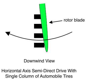
One drawback to the drive mechanism just described is that it must yaw with the rotor. One way around this problem is to employ a single large “tire” that encircles the tower, and that rotates about the tower. Or several tiers of tires encircle the tower, and each rotates at a different rpm and has its own generator.
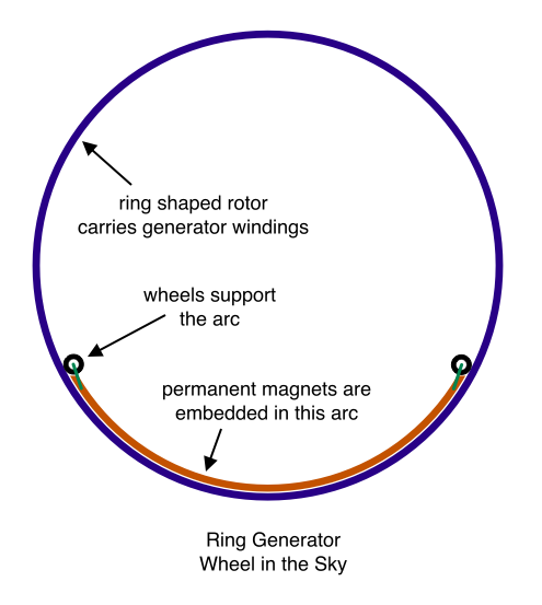
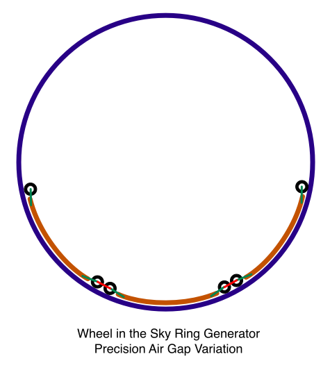
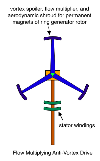
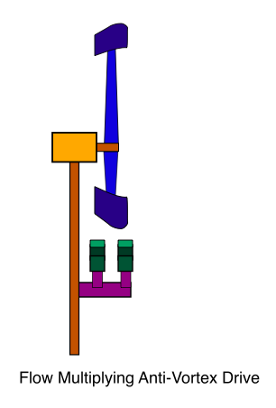
Of course, given the precision with which Scalable Darrieus blade motion may be controlled by the circular track, a more conventional (à la Enercon, Bergey) direct drive design may also be possible. (I hate to call the Enercon and Bergey drives “conventional”, since they are just so absolutely cool. But since they’ve been around for a number of years, I guess maybe they’ve earned the title.) In this more conventional approach, the Darrieus blade propels permanent magnets at high velocity near stationary coils that are embedded in or supported by the track. The moving parts in this drive are aerodynamically isolated from the wind that flows through the rotor by hiding them inside the circular track.
I have much more to say about this drive, and many variations to describe, but I’m tired now so I’ll update this post in the next few days with more info.
Advantages of the Scalable Darrieus Turbine
- Little Centrifugal Blade Load
There are two ways of scaling this machine – increase the height and increase the diameter. As previously demonstrated, the diameter can be arbitrarily large. When the diameter is large, blade motion is nearly linear. In this case, the large centrifugal loads that a traditional Darrieus must support are virtually non-existent in the scalable machine.
- The Scalable Darrieus Can Exceed the Betz Limit
As long as we’re going to be infinitely scalable, investors will eagerly agree that we may as well travel faster than light while we’re at it. If a sufficiently large diameter is selected, then the streamtube is re-energized by the time it reaches the downwind side of the rotor. The rule of thumb for separating horizontal axis turbines is that two turbines should not be closer than two or three rotor diameters. Apparently, after the streamtube has traveled two or three rotor diameters beyond the turbine, it will have absorbed kinetic energy from the surrounding wind to the extent that its energy density will have roughly returned to its original value. It’s easy to see how this will apply to a very large diameter Darrieus. Simply imagine a ridiculously large turbine. Say for example that the diameter of a Scalable Darrieus is equal to the diameter of Washington, D.C. Do you really think the wind that passes through the center of this machine (near the axis of rotation) will still be traveling with decreased velocity by the time it reaches the downwind side of the rotor? (It is of the utmost importance at this juncture to clearly distinguish the wind that passes through the nation’s capital from the wind that is generated from within its borders.) From this illuminating example we can see that the maximum fraction of energy that a very large diameter Darrieus may extract is 2 x 60% = 120%. Darrieus rotors have a reputation for delivering lower efficiency than their horizontal axis cousins. However, given the doubling of the ceiling on energy extraction, it is reasonable to believe that a very large diameter Darrieus may prove to be quite efficient. This is wonderful news, since one frequently cited reason for the gradual disappearance of the Darrieus from the windfarm landscape is that it has the larger weight per power ratio. The extraordinary scalability of the Darrieus described here may very well reverse this state of affairs.
- Efficient Use of Rotor Blades
The first diagram in this blog post depicts rotor blades that look more or less like the blades of a traditional Darrieus rotor. But it is obvious that this shape is not required for the Scalable Darrieus configuration. It would be perfectly reasonable to design a rotor with blades that are nearly vertical, like the blades of the so called “H Rotor”: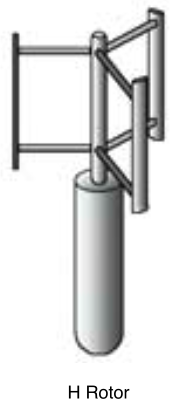 The H Rotor is very attractive from an aerodynamic point of view, but from a mechanical point of view it’s terrible. This is so because as its blades bow out, seeking the troposkein shape, a tremendous load is applied to the horizontal beams that support the blades. This load is in exactly the direction that the beams are least able to support (tending to pull the ends of the beams together). However, this is not a problem for the Scalable Darrieus rotor. First, the lever arm for the loads supported by the H Rotor beams is very long (extending from the tower to the blade). But exactly the opposite is true with the Scalable Darrieus design – the tower is close to the blades rather than the axis of rotation. Second, if the diameter of the Scalable Darrieus is large, then centrifugal loads are small, and the centrifugal load is partly responsible for the large vertical loads supported by the beams of the H Rotor. (The aerodynamic load is also responsible for this vertical load, and both the H Rotor and the Scalable Darrieus must bear this load.) The upshot is that the Scalable Darrieus rotor enjoys the favorable aerodynamic properties of the H Rotor, while suffering little of its mechanical drawbacks.
Getting sleepy… more advantages to come….
The Cheapest Electricity in the World
I’ve heard that hydro-electricity produced in the northwestern United States is the cheapest electricity in the world. I don’t know if this is still the case, but I think it was at least true for many many years, wasn’t it? The problem with hydro is that we have only a limited supply of it – they aren’t makin’ any more rivers. But the scalability of the Darrieus machine described here brings the nature of the wind resource into sharp focus. It is virtually unlimited. The challenge is continuing to overcome limitations in our ability to harvest it. In the early days of wind energy, people used to say “the wind is free”. One time I said that to a crusty old engineer who had been a leader in the development of the modern wind machine. He just gave me a stony look and said “yeah, but you can’t afford a wind turbine”. It saddens me that he’s not around to see that his years of fighting for a noble but unlikely cause really meant something. These days the scale of wind technology and its reliability increase every year, while the costs are falling dramatically. No one can fail to be impressed with the progress that dreamers, designers, and 10 below zero storm wind hands-on and practical 200 foot tower climbers have made in this field. And yet somehow it seems like there should be a way to push the increment well beyond the current 3 or 4 megawatts a pop, and up to the scale of some of the traditional power plant technologies. If it were possible to build a gigantic “history channel sized” civil engineering project with (say) 20 or 30 super-honkin’ 20 megawatt Darrieus machines in the Texas Panhandle… no…
Nooo…
NOOOO!!! NOOOO!!! A THOUSAND TIMES NO!!! Let’s find the biggest, stinkinest, 500 Megawatt smoke belchin’ power plant in the home of the free and the brave, buy up all the property around it, and use the 180 degree arc idea to surround that rattlin’ heap o’ scrap-iron WITH A ONE BOHUNKIN’ GIGAWATT SCALABLE DARRIEUS NO TRESSPASSIN’ FENCE!!! How better to showcase the power of wind and wind engineering to rival the output of a traditional power plant? And besides, it speaks to the most fundamental precept of uncivil engineering… indeed, of survival in the concrete jungle itself…
SIZE = RESPECT

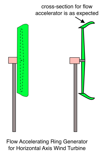
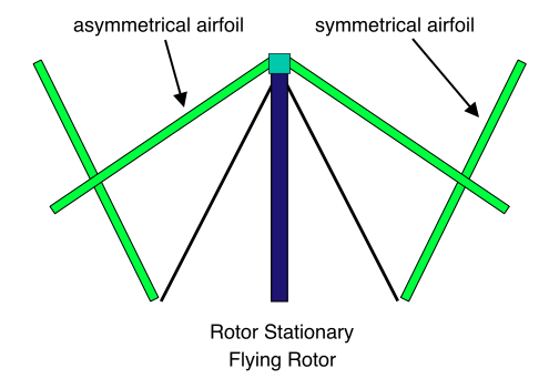
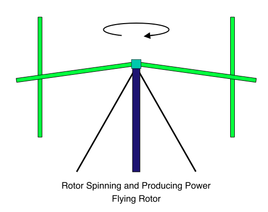
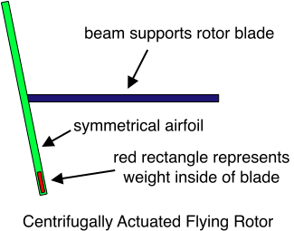
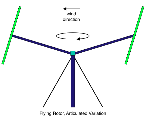


 The H Rotor is very attractive from an aerodynamic point of view, but from a mechanical point of view it’s terrible. This is so because as its blades bow out, seeking the troposkein shape, a tremendous load is applied to the horizontal beams that support the blades. This load is in exactly the direction that the beams are least able to support (tending to pull the ends of the beams together). However, this is not a problem for the Scalable Darrieus rotor. First, the lever arm for the loads supported by the H Rotor beams is very long (extending from the tower to the blade). But exactly the opposite is true with the Scalable Darrieus design – the tower is close to the blades rather than the axis of rotation. Second, if the diameter of the Scalable Darrieus is large, then centrifugal loads are small, and the centrifugal load is partly responsible for the large vertical loads supported by the beams of the H Rotor. (The aerodynamic load is also responsible for this vertical load, and both the H Rotor and the Scalable Darrieus must bear this load.) The upshot is that the Scalable Darrieus rotor enjoys the favorable aerodynamic properties of the H Rotor, while suffering little of its mechanical drawbacks.
