Salient White Elephant

May 10, 2009

CounterRotating Direct Drive Wind Turbine

A number of posts to this blog describe turbines (both HAWTs and VAWTs) having blades that are supported at the high-speed blade tips rather than at the low speed parts of the blades. This is usually accomplished by having a blade tip engage some sort of slot that is cut into a blade guiding track, so that the action is somewhat reminiscent of the way a rail guides the wheel of a train. One of the biggest problems with this approach is how to come up with a simple, reliable way of converting the kinetic energy of the blades to electricity. The conversion apparatus should not be unweildy or cumbersome, and should not require too much hardware. (For example, in some of my earlier posts I have suggested distributing generator windings all along a very lenghty blade guiding track. This is clearly undesirable because it would make the tracks very heavy and very expensive.)

I think I may have stumbled on a good way to deal with this problem just a minute ago while writing the post entitled: Skyscraper with H-Rotors. I didn’t do a very good job of describing the counter-rotating drive idea in that post, so I’ll attempt to do a better job of it here. (Although the technique described here may be applied to many of the HAWT and VAWT turbines proposed on the Salient White Elephant, you might want to read Skyscraper with H-Rotors first, since I’ll draw the diagrams and everything assuming that we’re applying the counter-rotating direct drive idea to that particular turbine.)

Counter-Rotating Direct Drive Wind TurbineThis turbine produces power in pulses. Each time two blades that are traveling in opposite directions pass each other, their generator components (permanent magnets and coils) pass close to each other as well. So a pulse of power is produced when two blades pass each other. Obviously, it would be better for a turbine to produce power at a smooth constant rate. This is desirable for many reasons. For one thing, producing power in pulses applies a cyclic fatigueing load on the mechanical components, and this is obviously bad news. For another, the electricity is easier to process and manipulate if it is produced at a smooth regular rate. But I am hypothesizing that the design proposed here may be a good one because it allows blades to be supported at both blade tips, even as both tips travel at high velocity! This is a tremendous advantage. But the main advantage of this design is that although it allows blades to travel long distances guided only by slots that are cut into blade guides, it does not require for these long distances to have generator components (magnets and/or coils) distributed along these long portions of the blade guides. Instead, the generator components are compact, and are attached to the ends of the airfoils. You can think of all of the airfoils that rotate (say) clockwise as comprising the generator “stator”, while all of those rotating counter-clockwise comprise the generator rotor. Of course, another disadvantage of this approach is that slip rings would be required to get the power away from the blades and into the electrical system. But there’s another advantage as well – the fact that the generator’s rotor and “stator” rotate with equal and opposite rpm’s effectively doubles the relative speed with which the coils and magnets pass each other.

So before closing, let me address one of the biggest disadvantages of the idea proposed here – that power is produced in pulses. First of all, the fact that generator rotor and “stator” components are counter-rotating means that more pulses per second are produced than you might otherwise expect. (The more pulses the better. If we had enough pulses then they’d all bunch together and we’d have continuous power. As a matter of fact, three phase power is produced in pulses as well, yet these pulses combine to produce power that is perfectly constant. Might we find a way to exploit this three phase effect to make the power output from this machine constant? Don’t know, and too tired to think about it right now, so maybe I’ll revisit this later. But anyway it may not matter. I’m not concerned about the electrical pulsing – we can easily deal with that using power electronics. I’m more concerned about the pulsating mechanical loads, because these will fatique mechanical components and cause them to fail. On the other hand, the good news is that this pulsating load is confinded with a small space that is enclosed by the slots that guide the blades. This is good, because the more confined it is, the more options we have for dealing with the cyclic load. One option being, for example, just beefing up the support structure in that area. This is possible because, again, this area is aerodynamically shielded from the outside wind because it lives inside the slot.) Anyway, as I said, the because the blades are counter-rotating, they pass each other at a relatively high frequency. So maybe we can just design the machine to have many small blades (i.e. many blades, each having a short chord). Now when all these blades counter-rotate, we may end up with so many pulses that the output power looks like DC with a ripple on top. (Remember that adjacent blades don’t necessarily need to be separated by a constant angle. For example, just because there are (say) 6 blades that rotate (say) clockwise doesn’t mean that each adjacent blade must be separated by an angle of 360/6 = 60 degrees.)

Ring Generator Option

If the pulsating loads turn out to be a showstopper, then we can always fall back on the ol’ ring generator approach. In this case, we have the advantage that the rings are counter-rotating, thus doubling the velocity between magnets and coils.
April 3, 2009

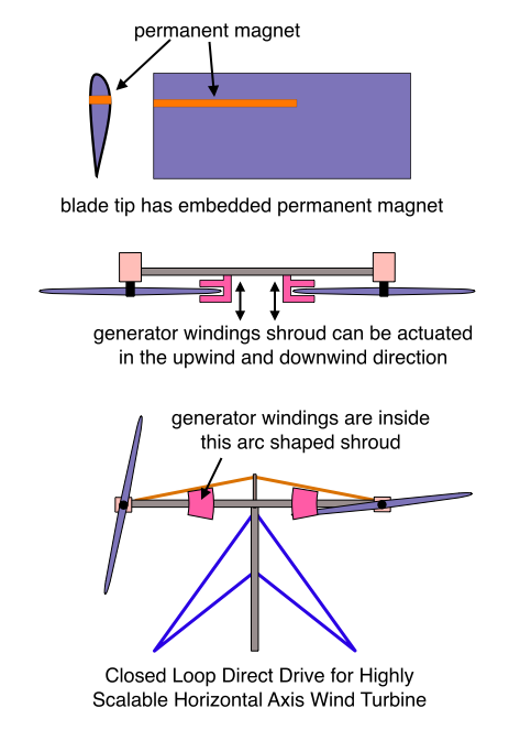
Closed Loop Direct Drive for Highly Scalable Horizontal Axis Wind Turbine

Closed Loop Direct Drive for Highly Scalable Horizontal Axis Wind Turbine

This drive system has sensors in the turbine blade that measure how much each blade is bent by lift and other forces. The shrouds that house direct drive generator windings are moved in the upwind or downwind direction in order to properly position them for the approaching turbine blade. What kinds of sensors might provide the proper information to the closed loop control system that adjusts the position of the generator windings? I don’t know. Strain gauges embedded into the blade spars that communicate with the controller via a radio link? A cylindrical cavity inside the blades that runs in the longitudinal direction and that has a laser at one end and a mirror at the other?

Another idea would give the turbine blade a permanent magnet that can protrude (longitudinally) from the blade tip. With this design, the shroud that houses the generator windings move to a location that is completely outside of the rotor disk (i.e. the swept area). As a blade approaches the windings, its magnet is pushed out of the blade tip. Once it passes the generator windings, the magnet is retracted so that it doesn’t create drag during the rest of the blade’s trip around the rotor disk.

Well it’s a couple of days after I wrote this, and re-reading it, it seems like a pretty stupid idea. I guess I just keep thinking about how once the turbines starting getting really big (1 megawatt or so), then the really sexy power electronics came onto the scene. Making this blog has proven to me that wind turbine innovation is likely to come from integrating other already well-known technologies, like power electronics. They didn’t invent power electronics for wind turbines, but once the machines got big enough to justify the cost of integrating these well understood devices and circuits, the addition of them provided much improved performance, and probably cut the cost of energy as well. So I’m just thinking that closed loop control technology might be one of the next things. Like for example, suppose it’s difficult to manufacture a giant ring generator and still maintain the tight tolerances required for good performance (given temperature changes, etc). Then maybe strain gauges of other sensors could be added, and a closed loop control system could adjust the radius of the rotor or stator at various angular positions… kind of like the way you turn the little nut-like things on a bicycle wheel to make it perfectly round and so that it won’t wobble side to side. So instead of trying to make the perfect ring generator, you just let the control system continually adjust the various tolerances based on sensor readings taken every minute or so. One thing’s for sure… pretty much every wind turbine configuration that can be thought of has already been thought of over all these centuries. So I wish I was in a position to look at how other technologies might be integrated in order to lower the cost of wind electricity… but I’m just not in a position like that. (Another thought that comes to mind is self-health checks… like they have in avionics systems… they have raised the detection of equipment failure or underperformance or abnormal performance to a high art form.)

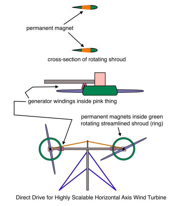
Magnets In Rotating Shroud

Magnets In Rotating Shroud
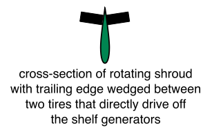
This design is applied to the Highly Scalable Horizontal Axis Wind Turbine. I would put the rotating shroud on the other side of the nacelle, away from the blades, but that would require the mechanical power to go through the shaft, and I was trying to avoid that. I wonder if you could just have a rotating shroud with no magnets in it, and wedge its trailing edge between two tires and directly drive an off the shelf generator?

Rotating Shroud Drives Tires

March 27, 2009

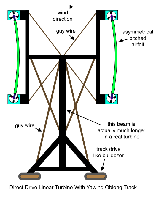
Direct Drive Linear Turbine With Yawing Oblong Track

Direct Drive Linear Turbine With Yawing Oblong Track

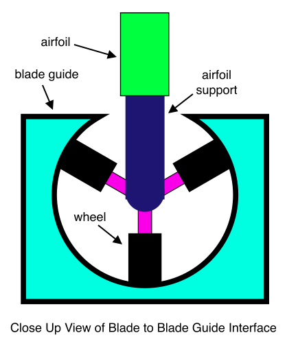
Direct Drive Linear Turbine With Yawing Oblong Track, Close Up View of Blade to Blade Guide Interface

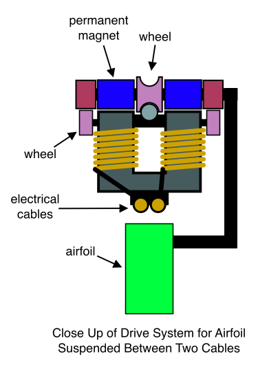
Although the direct drive apparatus isn’t shown in the diagrams, a written explanation should suffice. Permanent magnets are attached to the blade supporting structure that is at each end of the airfoils. The airfoils drive these magnets at a speed that is analogous to the “tip speed” of a more traditional wind turbine. Generator windings are built into the blade guides (aqua colored components in diagram above). Instead of embedding windings into the entire length of the blade guides, windings are separated somewhat. Blades speed up slightly while traversing the distance between windings.

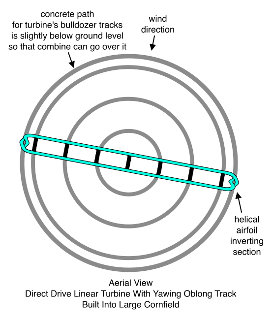
Direct Drive Linear Turbine With Yawing Oblong Track, Aerial View

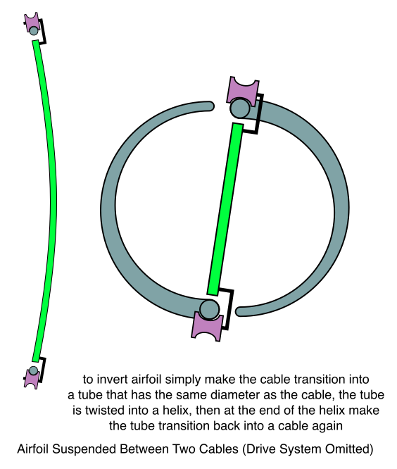
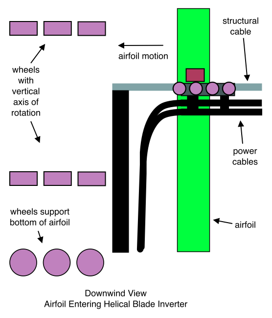
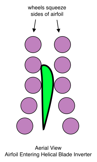
The blade inverting sections of the track permit the use of asymmetrical, pitched airfoils. (Asymmetrical, pitched airfoils deliver better aerodynamic performance than zero-pitch, symmetrical airfoils. For an explanation of the “helical airfoil inverting section” of the track, see my earlier post: 20 Megawatt Direct Drive Darrieus.)

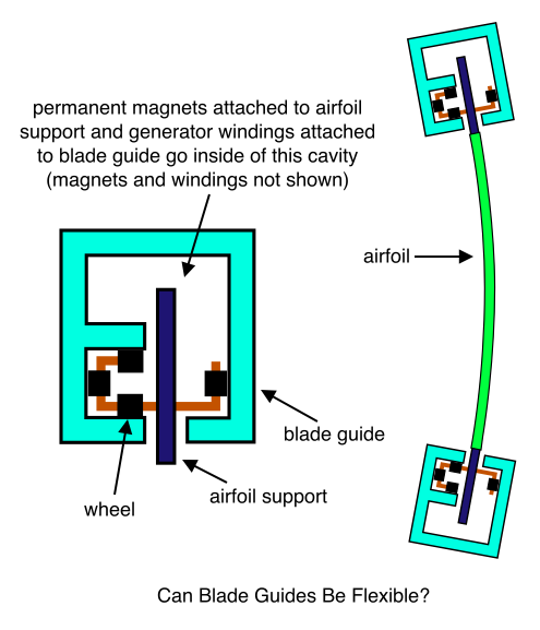
I wonder if the blade guides can be flexible? If so, the flexibility may provide a number of benefits. For one thing a flexible guide might be cheaper, lighter in weight, and easier to build. For another, it may help to absorb abruptly changing loads due to (for example) wind gusts. It might be interesting to explore the possibility of a blade guide which is flexible enough to resemble, to a degree, a hanging cable, and yet which is still rigid enough to accurately maintain the tight mechanical tolerances that would be required for the direct drive generator components contained within it:

Can Blade Guides Be Flexible?

Two Hanging Cables Variation

Airfoil Suspended Between Two Cables (Drive System Omitted)

(If you haven’t yet read about why you might want to invert the blade, click here.)

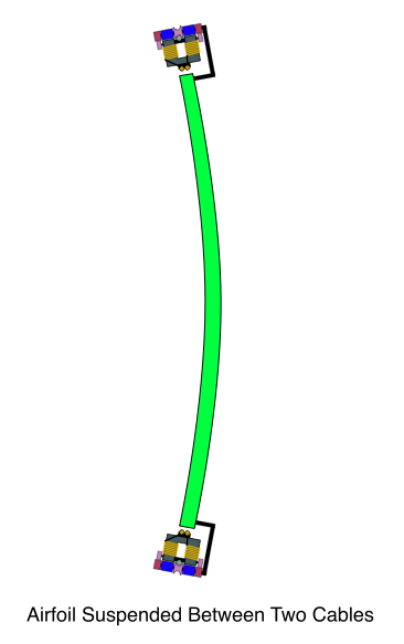
Airfoil Suspended Between Two Cables

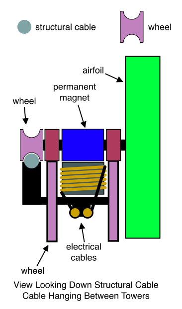
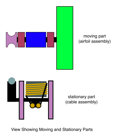
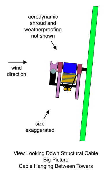
Close Up of Drive System for Airfoil Suspended Between Two Cables

It might be interesting to explore how the Eye of the Cat Rotor Blades would perform when hanging from two cables. Although there’s no centrifugal forces to balance, remember that the Cat’s Eye Rotor also balances aerodynamic forces. In this case, think about what happens if the blades are longer than the separation distance of the cables (including slack… so that they tend to keep the cables pushed apart).

Single Hanging Cable Variation

In this variation, sensors detect when two airfoils get too close to each other. In this case, the direct drive generator coils for the leading airfoil are switched off until it reaches an acceptable distance from the airfoil immediately behind it.

View Looking Down Structural Cable Cable Hanging Between Towers

View Looking Down Structural Cable, Moving and Stationary Parts, Cable Hanging Between Towers

View Looking Down Structural Cable, Big Picture, Cable Hanging Between Towers

Downwind View, Airfoil Entering Helical Blade Inverter

Aerial View, Airfoil Entering Helical Blade Inverter

March 24, 2009

Radially Displaced HAWT Rotor

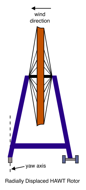
Radially Displaced HAWT Rotor, Side View

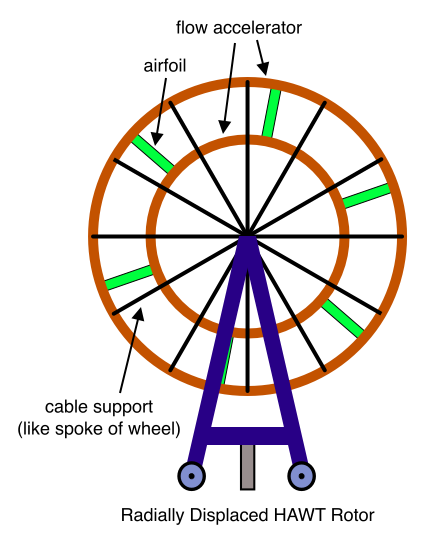
Radially Displaced HAWT Rotor, Downwind View

Only the airfoils rotate in this machine. The flow accelerators are supported in the manner of a wheel with spokes. Each end of each airfoil is attached to a cable that moves like a rotating ring inside of its flow accelerating shroud. The cables drive the generators. (Generators not shown in diagram.) Alternatively, the flow accelerating shrouds can house direct drive generators in the manner described in an earlier post entitled Flow Accelerating Ring Generator for Horizontal Axis Wind Turbine.

It might be worth considering a combination of this idea and the one described in Highly Scalable Horizontal Axis Wind Turbine.

March 20, 2009

Wheel in the Sky

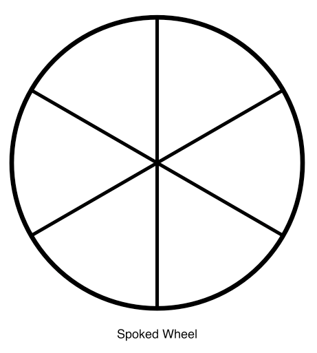
This is a horizontal axis machine. Imagine a giant wheel with six spokes – three upwind and three downwind:

Spoked Wheel

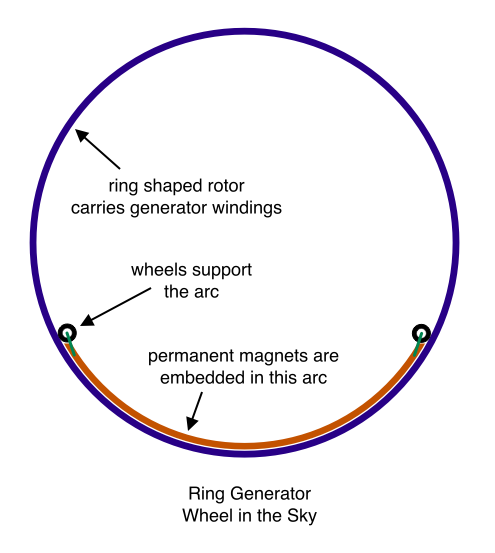
The spokes are airfoils. The rim simultaneously provides three functions – it is a vortex spoiler, flow accelerator, and it is an aerodynamic shroud that contains the parts of a giant ring generator. Just as the spokes of a wheel rotate with the wheel, the aerodynamic rim rotates with the turbine blades. Generator windings are embedded in the rim along its entire circumference. The permanent magnets are embedded in a component that is shaped like a 60 degree arc. (I’m not sure how many radians the arc needs to sweep. I’m just guessing it might be in the neighborhood of 60 degrees.) When the turbine isn’t turning, the 60 degree arc rests on top of the ring that carries the windings in the 6 o’clock position. The arc has wheels beneath it that regulate the small gap between the magnets and the surface of the ring that carries the windings:

Ring Generator, Wheel in the Sky

Now when the turbine rotor begins to turn, the arc with its magnets will turn as well. However, it won’t turn very far before the gravity generated counter-moment will balance the force that tends to drag it along with the (generator) rotor. At this point the machine will begin to produce electricity.

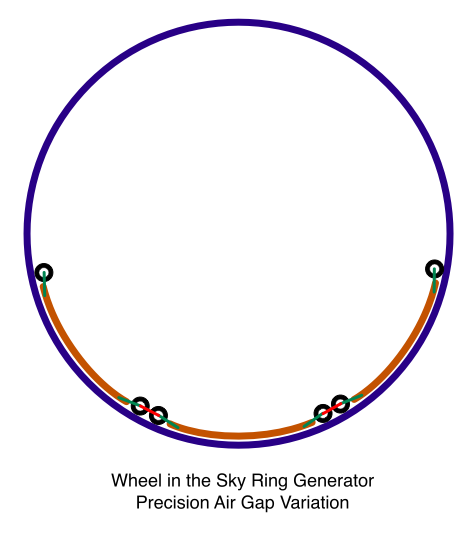
Precision Air Gap Variation

This variation employs segmented arcs that are connected end-to-end. This allows the air gap to be independently and accurately regulated for each stator segment:

Wheel in the Sky Ring Generator, Precision Air Gap Variation

Advantages and Disadvantages of Wheel in the Sky

It is unfortunate that the outer surface of the aerodynamic ring must travel at blade tip velocity. This will certainly generate a great deal of turbulence. But consider the benefits:

  • diminished blade tip vortices,
  • accelerated flow near blade tips,
  • airfoils supported at both ends (lighter, stronger airfoils),
  • low noise (six blades mean diminished rotor rpm),
  • precision direct drive generator,
  • extremely large diameter ring generator (high speed generator rotor),
  • zero torque main rotor shaft.

That’s an impressive list of benefits. Will these advantages outweigh the aerodynamic losses of the rotating rim?

By the way, it might be a good idea to combine the Wheel in the Sky and the Highly Scalable Turbine.

March 19, 2009

Flow Multiplying Anti-Vortex Drive

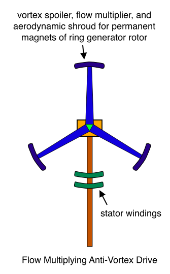
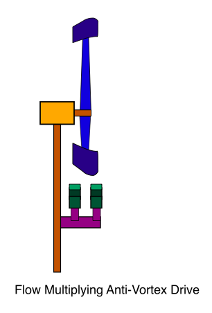
This machine has a blade tip that simultaneously performs three functions. It is a kind of elongated, arc-shaped vortex spoiler, and it is pitched relative to the oncoming wind so that it also accelerates flow through the rotor disk. It’s third and final function is to streamline and support the permanent magnets of a direct drive ring generator:

Flow Multiplying Anti-Vortex Drive

Flow Multiplying Anti-Vortex Drive

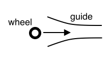
How can the (generator) rotor pass through the stator without hitting it and still maintain the close tolerances that are required? I don’t know, but perhaps some sort of guide system can be designed that routes it through the stator. The following diagram gives the general idea. It shows a wheel approaching a guide. The wheel is not necessarily aligned with the guide, but the funnel-like shape of the guide causes it to make any necessary adjustments in position.

router

One disadvantage of the Flow Multiplying Anti-Vortex Drive is that the structure housing the stator coils must yaw with the nacelle and rotor. However, if the drive idea is used together with the Highly Scalable HAWT idea, then the stator coils may remain fixed, and do not need to yaw with the rotor blades.

Blog at WordPress.com.