Salient White Elephant

May 12, 2009

Jet Stream Ram Air Wind Turbine

In earlier posts I have mentioned that a turbine capable of harvesting the energy of jet streams would probably be better for newspaper headlines than for an economical approach to wind electricity, since it would probably be cheaper and more effective to build several smaller low altitude turbines than a single monster that could tap into the jet streams. But it got me to realize that there are no jet stream turbines on the Salient White Elephant. This is Salient, to be sure, but is it White Elephant? Certainly not! And already I can hear not a little hubbub from the Canadian Parliament behind me patting their tables and gushing heah heah! So let’s just round things out with a couple of jet stream turbines before tensions run too high and one of the hairs on the head of the Right Honourable Stephen Harper springs noticeably out of place, shall we?
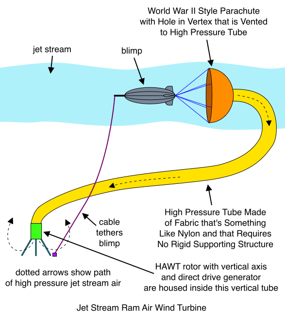
Jet Stream Ram Air Wind Turbine

For some reason, I’m usually biased toward using suction rather than high pressure in my flow accelerator ideas. But one advantage of using ram air pressure in the machine proposed here is that it would keep the long fabric tube inflated. This is very significant of course, since one of the biggest challenges in designing an airborne turbine is keeping weight to a minimum. Using high pressure might eliminate any rib-like supporting structure that would otherwise be required for the tube. I guess you’d have to stabilize the fabric tube by attaching it to the tethering cables at various intervals, but who knows… maybe somebody can design a way around this requirement.

Triple Tethered Variation

Jet Stream Ram Air Wind Turbine, Triple Tethered Variation

Multiple Blimps Variation

There are many variations of the ideas proposed here, but let me discuss one in particular. This idea emphasizes a technique I’d like to use to bring these pie-in-the-sky airborne turbines a little closer to feasible. Imagine eight blimps. Each is tethered by at least three cables to keep the blimps from moving around too much. An aerial view would reveal that the blimps are situated at the vertices of a gigantic octagon. It is important to note that the “diameter” of the octagon is far from insignificant. I can’t give you a number… maybe two or three football fields? Each blimp has a parachute and a high pressure tube, just as described above. All of the high pressure tubes converge at the center of the octagon, where they connect to a single larger high pressure tube that takes the jet stream wind down to the ground.

What’s so great about this variation? Well… let me first list what I believe may be the salient objectives of airborne turbine design:

  • If possible, no moving parts in the air.
  • If possible, no fiberglass, electrical cable, gearboxes, drive shafts, or electrical generators in the air. (Ever notice how the components of a wind turbine that have to do with mechanical and electrical power are about the most dense (heaviest) things known to engineering kind?!)
  • MINIMIZE WEIGHT, MINIMIZE WEIGHT, MINIMIZE WEIGHT!!!!!!!!!!!

So the idea here is that instead of having eight different tubes, we attempt to minimize weight by having a single large tube carry wind from the jet stream to the ground. This is desirable because the really long distance is from the jet stream to the ground. Once at the center of the jet stream octagon, it isn’t much further to the blimps. So could we use this trick to reduce the overall weight of the machine?

Well, whether this trick will work or not… I think you see my point. What is needed is a kind of linear programming style optimization that minimizes weight of fabric per kilowatt of capacity.

Can We Really Reach the Jet Stream?

No. The jet streams are like 30 to 40 thousand feet off the ground. (The cruising altitude of jet airplanes!) So we can’t reach the jet stream with the design proposed in this post. But we can certainly reach a higher altitude than today’s state of the art wind turbines! If you want to see a more practical configuration that uses the principles described in this post, check out the Practical Artificial Pressure Differential Wind Turbine.
April 27, 2009

Blimp Supported Linear Turbine

Filed under: Airborne Wind Turbine, Linear Wind Turbine — Tags: , — Salient White Elephant @ 8:40 pm

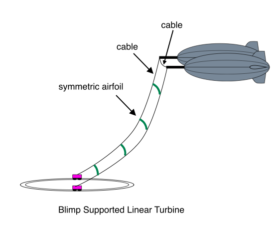
Blimp Supported Linear Turbine

There’s not much detail in the diagram, and much has been omitted. But I’ve drawn all the mechanisms involved so many times on this blog that I don’t think I’ll draw them again. But let me explain how it works. Heavy cables connect the blimps to the ground and carry the large loads. The symmetrical airfoils travel from the ground to the blimp and then back to the ground again. These airfoils are supported at either ends by moving cables (not shown) that turn a bunch of pulley wheels. The pulley wheels are suspsended from the heavy cables. Power is transmitted from the airfoils through the pulley system to a couple of generators at ground level. Each rail car has one of these generators on top of it.

Alternatively, replace the airfoils in the diagram with relatively small diameter Darrieus or H rotors. Power is still transmitted to the ground mechanically with a pulley system.

Airborne Wind Turbine Energy Multiplier

Filed under: Airborne Wind Turbine — Tags: — Salient White Elephant @ 6:22 pm

Suppose an airborne turbine can choose its altitude, as in the various blimp supported turbines proposed on this blog. In this case, the blimp may choose to hover in the clouds if it’s a cloudy day. Since the air in the clouds is wet, won’t its density be greater? And since the energy in the wind is proportional to density, then won’t this mean that the wind in the clouds will have more energy? Of course, the blimp may not be able to reach that altitude, but if it can, then here’s a possible option for increasing the amount of energy harvested.

About an hour after I posted this, I read in Wikipedia that the density of air actually decreases as a function of humidity. I was quite surprised to read this, but if you don’t believe me, check out the Wikipedia article for yourself. The reason it decreases is that “the molecular mass of water (18) is less than the molecular mass of air (around 29)”. One of my earlier posts suggested increasing the energy density of wind approaching a turbine by injecting a fine mist into the wind in some upstream location. (I was thinking of those misting devices they have to cool people down on the patios of some coffee shops and restaurants.) The Wikipedia article raises an interesting question. Is air that carries a fine mist “humid air”, or is it air that is carrying droplets of water? Because for the Wikipedia analysis to apply, the water must be in a gaseous state. And what about clouds? The stuff that falls on our heads on a rainy day certainly isn’t a gas. Well… it’s late, and I hope you guys will be able to sleep without knowing the answer to this compelling mystery… because I’m going to sleep! More on this later…

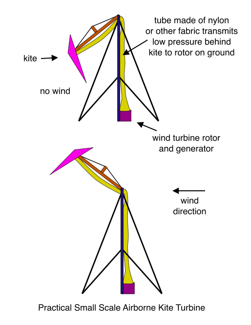
Practical Small Scale Airborne Kite Turbine

Practical Small Scale Airborne Kite Turbine

There’s a hole in the middle of the kite that the tube connects to so that the tube can reach the low pressure behind the kite.

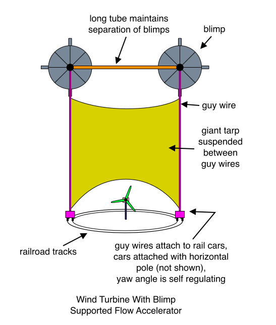
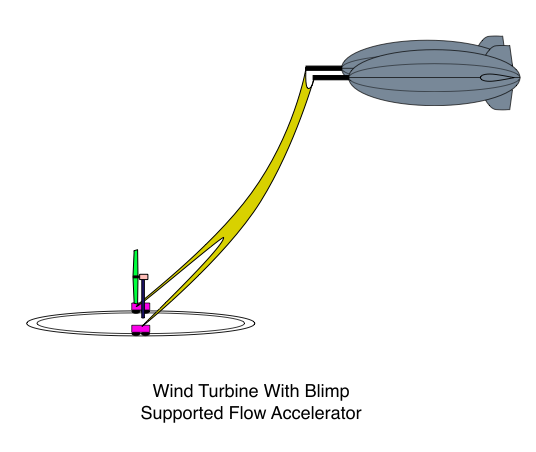
Wind Turbine With Blimp Supported Flow Accelerator

Wind Turbine With Blimp Wind Turbine With Supported Flow Accelerator

Wind Turbine With Blimp Wind Turbine With Supported Flow Accelerator

Ultra High Altitude Low Visual Pollution Variation

There are a few problems with the turbine just described:

  • The weight of the suspended tarp may be prohibitive.
  • The tarp resource is poorly leveraged because much of the wind it redirects is low-energy wind that is close to the ground.
  • The blimp resource is poorly leveraged because much of its size and weight stems from the need to support the large part of the tarp that is close to the ground.
  • The blimps are not able to fly at high altitude because the tarp would simply be too heavy to lift to high altitude.
  • The exceedingly powerful suction developed by such a large flow accelerator may reverse the flow that is near to the ground and not too far above the turbine and the lower edge of the tarp.

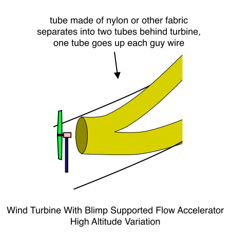
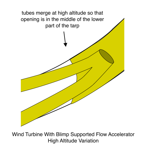
This variation proposes to solve these problems and permit extremely high altitude wind to be harvested:

Wind Turbine With Blimp Supported Flow Accelerator, Side View, High Altitude Variation

Wind Turbine With Blimp Supported Flow Accelerator, Side View, High Altitude Variation

Now the blimps and tarp may be separated from the turbine by a very large vertical distance, and the suction is carried to the ground through light-weight fabric tubes that are supported on the guy wires. As an alternative to the design shown above, one tube can be fixed to carry high pressure and the other can carry low pressure. The turbine is then placed between the openings of these two tubes at ground level.

I wonder if this design or something like it would be capable of reaching the jet streams? I guess that’s pretty outrageous, and probably not even necessary. (It may be more economical to harvest lower altitude winds using several machines than to build a single gigantic machine that reaches the jet stream. Plus you’d have the safety issue – what if a cable breaks? Of course, I guess you could always put it out in the ocean. Another potential problem with extremely high altitudes is that the wind direction up there might not be the same as on the ground. But then again, if you’re getting so much energy from altitude, you could just put the turbine rotor inside the tube, and also put the rotor on the ground so that it doesn’t have to yaw. This way the wind velocity near the ground would be insignificant compared to the velocity of air moving through the tube, and so it wouldn’t matter which way the rotor were pointed, or which way the opening of the tube were pointed. In fact, you could use a HAWT rotor that spins about a vertical axis, and let the tube extend from the rotor in the vertical direction.)

April 24, 2009

Airborne Savonius

Filed under: Airborne Wind Turbine, Savonius Wind Turbine — Salient White Elephant @ 8:37 am

Three giant helium filled balloons are shaped like the “blades” of a Savonius turbine. The balloons float up in the sky, and transmit power to the ground through a rotating drive shaft or a rotating cable.

April 23, 2009

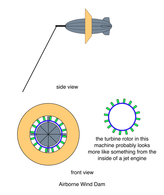
Airborne Wind Dam

A blimp suspends a giant flow accelerator with a small high-power turbine in the middle of it. In other words, a blimp suspends a turbine that looks kind of like the one described in this earlier post:

Wind Turbine with Flow Accelerating Shroud

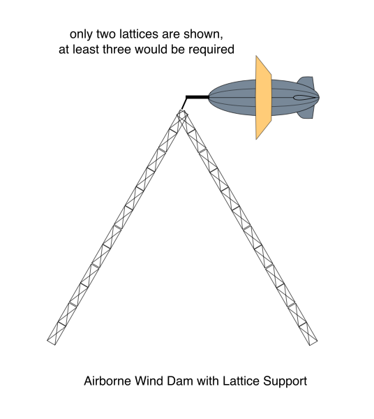
This rotor will spin at high rpm, so it is easy to make it a direct drive machine. As described in prior posts, the bottom of the flow accelerator can attach to the top of a supporting tube in order that the blimp doesn’t have to carry the entire gravity load of the shroud and turbine. The tube is on wheels and a control system causes it to follow the blimp around with changing wind speed and direction.

Here’s another variation:

Airborne Wind Dam

Airborne Wind Dam with Lattice Support

Blimp With a Hole Variation

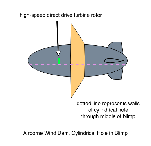
In this variation, the blimp has a cylindrical hole right through the middle of it (running down its longitudinal dimension). The small high-speed direct drive turbine rotor is inside this cylinder. A large shroud like the ones depicted above encircles the blimp in order to further accelerate flow through the cylinder and direct drive turbine rotor.

Airborne Wind Dam, Cylindrical Hole in Blimp

Skyscraper Variation

In this variation, the blimp is moored to the top of a skyscraper. When the windspeed gets too high the blimp simply detaches from the building and flies to a nearby airport where it lands until the storm passes. I hate to make the next suggestion, because somebody might actually do it. The blimp could be moored to the top of a mountain. This would produce a lot of visual pollution, so I don’t think it’s a very good idea.

Lightweight Electrical Components Variation

The blimp is big and round. It has plenty of room for a ring generator. Of course, you don’t need a ring generator to make this machine direct drive, because the accelerated flow through the cylinder is already sufficient for making the turbine rotor spin at high rpm. But if the turbine drives a very large diameter ring generator, then electricity can be generated with high voltage. If voltage is high, then current is low, and the weight of electrical components such as the electrical cables is minimized. (I’m assuming insulation weighs less than copper.)

Structural Electrical Cable Variation

This option develops electrical cable technology that is suitable both for conducting electrical power and for carrying a tensile mechanical load. This minimizes the weight of the mooring cable, since the electrical cable simultaneously provides both mechanical and electrical functions.

Aerodynamic Transmission Variation

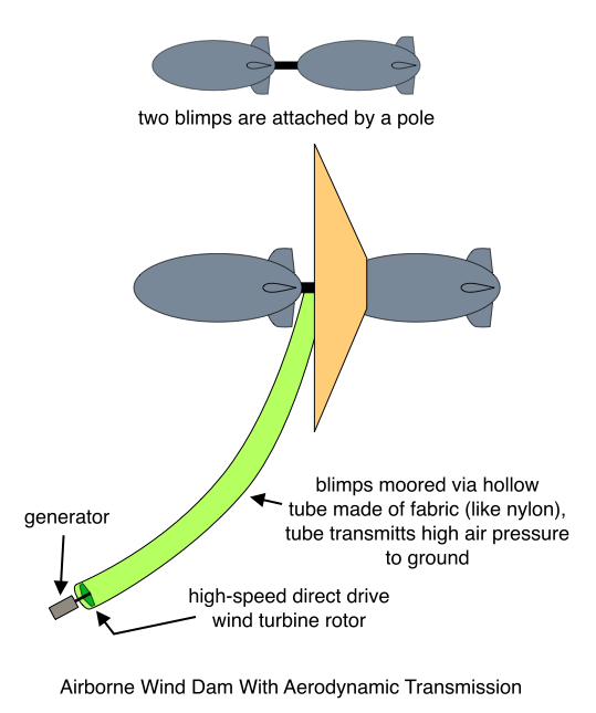
The diagram below is a little ridiculous, but I’m a terrible artist, and I’m using 2D software to create these diagrams, so for this diagram I decided to come up with something that just shows the general idea. And the general idea is to reduce the weight of airborne components by using a light-weight hollow tube to moor the blimps. The hollow tube transmits the high air pressure that accumulates at the center of the dam (shroud) to the ground. A small high-speed turbine rotor drives a generator at the ground level end of the tube. The turbine rotor is high speed, and so it doesn’t need a gearbox. The airborne system carries no electrical or mechanical devices, and so it is light in weight.

Airborne Wind Dam With Aerodynamic Transmission

This idea suggests an interesting question – what happens to the Betz Limit when de-energized air doesn’t flow away from the turbine on the downwind side of the turbine “rotor”?

Of course, the aerodynamic transmission may also be applied to more convention turbine designs. Perhaps a shroud is positioned at the top of a conventional wind turbine tower, and the tower itself is used to route the high pressure air to a turbine rotor and generator on the ground.

Pressure Differential Aerodynamic Transmission Variation

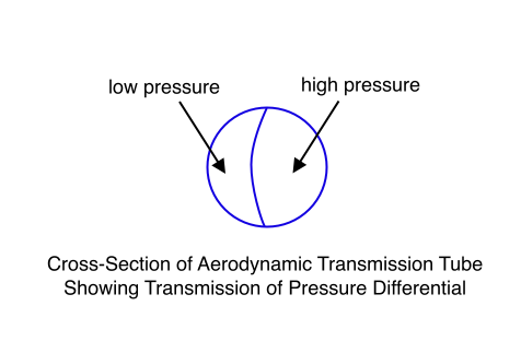
A wall is added to the inside of the aerodynamic transmission tube. This separates the tube into two halves, just as though there were two tubes instead of one. One half of the tube opens on the high pressure side of the shroud, and the other half opens on the low pressure side. This pressure differential is carried to the ground where one side of a high-speed turbine rotor encounters the high pressure, and the other side of the rotor encounters the low pressure. Air thus flows through the rotor and turns an electric generator.

Cross-Section of Aerodynamic Transmission Tube Showing Transmission of Pressure Differential

Rotating Drive Shaft Variation

Hollow, light-weight, rotating tubes are connected end-to-end through universal joints. The tubes are attached to the mooring cable and so are suspended beneath the mooring cable. A high-speed rotor at the top transmits power to the ground through the rotating drive shaft tubes. The spins at high rpm so drive shaft torque is low.

Reciprocating Blimps

Two blimps are moored to each end of a horizontal tube or lattice structure that is near the ground. The tube rotates about a vertical axis that goes through the center of its longitudinal dimension. Each blimp is equipped with a giant light-weight parachute that looks like an old World War II parachute. These parachutes can be opened up to create a high drag profile, or closed to create an extremely low drag profile. When one blimp opens up its parachute, the other closes its parachute. The blimps take turns opening their parachutes in order for the wind to drag alternately drag each in the downwind direction. The reciprocating action of the horizontal mooring tube drives a generator.

Alternatively, perhaps a large “venetian blind” structure hangs from each blimp. The slats in these blinds can be opened up to create near zero drag profile, or closed to create a high drag profile. This variation is modeled after the turbine depicted below:

Here’s an embodiment that uses venetian blind like slats:

One of a Pair of Reciprocating Blimps

Rotary Variation

This is the same idea, except that the horizontal tube rotates instead of reciprocating. As the end of the tube begins its 180 degree “downwind sweep”, the blimp that is moored to it closes its slats to create maximum drag, and the other blimp opens its slats to minimize drag.

Adding HAWT Rotors

Instead of using drag devices, a giant HAWT rotor can be attached to the tail of the blimp. The rotor has very long, very light weight blades that rely on centrifugal stiffening to maintain their extended shape. These minimize drag by feathering their blades, and maximize drag by pitching their blades to a position similar to a HAWT turbine that is producing power. The drag action is similar to the lifting action of an autogyro. In other words, the HAWT rotors are not present to generate power directly. They are only present to control the drag profile of the blimp. On the other hand, perhaps a means can be devised for allowing them to augment the power produced by the system. In order to keep the weight of airborne components to a minimum, they do not produce very much electricity, but they do add a little bit to the electricity that is produced on the ground.

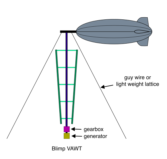
Blimp VAWT

Since no people will ride in the blimp, I guess it could be filled with hydrogen.

Blimp VAWT

I’m always drawing 2 bladed VAWTs when I really mean 3. A three bladed VAWT produces relatively constant power, and more importantly in this case, thrust. Since wind speed will normally increase with altitude, blade radius increases with altitude so as to maintain a more constant tip speed ratio. For simplicity, I drew only 2 guy wires. In reality, at least three would be required.

The turbine’s rotational axis can tilt, and the gearbox and generator tilt along with the rotor axis. This allows the wind turbine to seek its optimum orientation given wind speed and other parameters. Alternatively, perhaps the lower end of the wind turbine (the generator) is on wheels and is able to move if the turbine wants to move. Since the structure will be very heavy, the control system would likely control the movement of the generator this way and that along the ground as wind conditions change. But if we let the lower end of the turbine move, then we may as well save some weight by using only one guy wire or lattice to moor the blimp. In this case, the turbine will “yaw” by roughly tracing out a circle about the guy wire anchor point as the wind direction sweeps through a 360 degree arc.

The teardrop streamlined shape of the blimp is critical. If any old shape is used for the floatation device, then the wind will tend to carry it downstream. I don’t know what the optimum aerodynamic profile would be, but you would want to minimize drag. For this reason, perhaps a very elongated shape (kind of like a cigar) might be used.

Kites and Airfoils

Additional lift may be generated if a kite is positioned on top of the blimp. Imagine, for example, those modern parachutes that look like a big airfoil made out of something like nylon. If one of these is mounted on a vertical pole that extends upward from the blimp, then it will “take flight” when the wind speed reaches a sufficient value. In this case it will be available to add further support for the turbine whenever the turbine is running and producing power. Some kind of inflatable airfoil might do the same trick. If a kite or modern parachute is used, it will be suspended by its supporting structure in a shape and orientation that “prepares it” for taking flight when the wind picks up.

Other Variations

I think there must be many ways to develop better configurations if more than one blimp is employed. For example, two blimps could be moored to a giant circular railroad track. The anchor points are “yawed” so that a line connecting them forms a right angle with wind direction. The blimps are connected by a cable, and multiple VAWT turbines are suspended from the cable that connects the two blimps.

Weight is obviously one of the primary issues with airborne turbines. Perhaps some sort of inflatable airfoils can be used. The airfoils may even themselves be filled with hydrogen. Or a design similar to those light-weight modern parachutes might be used for the blades.

Create a free website or blog at WordPress.com.