Salient White Elephant

August 7, 2009

Summary of the Best Ideas on the Salient White Elephant

Since there are currently 127 posts on the Salient White Elephant, I thought it might be a good idea to devote this post to summarizing the best of these ideas.

Big Wind or Small Wind?

A worldwide network of inexpensive desktop computers ultimately proved to be far more powerful than the super computer. This lesson should not be lost on wind enthusiasts. However, the Salient White Elephant has proposed intriguing ideas both for very large wind turbines as well as for small wind turbines that may be deployed in large numbers. So why not experiment with both, and let the market sort the winners from the losers?

Idea #1) Circular Wind Dam
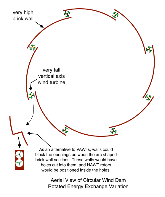
Circular Wind Dam

Advantage Over Flow Concentrators and Diffusers

Flow Concentrator and Diffuser

Increasing the outer diameter of a shroud in order to squeeze more wind through a turbine rotor causes the wind to develop greater tendency to veer around the entire structure – shroud, rotor, and all. For this reason, the laws of fluid mechanics tell us that you can squash only a limited amount of “extra wind” through the small opening that contains the rotor. But the wind dam is not subject to this limitation. Why not? Because the purpose of its flow manipulating structure is not to “contain the wind”, but rather to force it to do what it already wants to do – to veer around the entire flow manipulating structure! This effect can be increased indefinitely by building larger and larger dams. In this case, having nowhere else to go, the wind is obliged to flow around the entire structure, regardless of how big it is!

Another obvious advantage of the wind dam is that it is stationary and attached to the earth. A concentrator or diffuser must be suspended high in the air, and must be yawed with the machine. The shroud is large, poorly supported, and vulnerable to mechanical failure.

Here’s a link to the original Circular Wind Dam post. (I wonder if an offshore version of this idea would be possible in shallow water. In this case, the underwater part produces hydro power and the above water part produces wind power. One nice thing about combining the hydro and wind is that it would probably increase the net capacity factor. Also, it seems like it might be possible to design the underwater part to harvest both tidal and wave power.)

Idea #2) High Capacity Factor Wind Turbine

A very large wind turbine with a flow accelerating component (like the Circular Wind Dam just described) is designed to have a very low cut-in wind speed. The turbine is also designed to be very inexpensive through the removal of weight, leaving it perhaps even flimsy. Structural integrity is achieved by providing the machine with ample means for shedding the energy of higher speed winds, and for allowing storm winds to pass through the structure virtually unimpeded. (Perhaps a wall has slats or portholes that can open and close.)

Now because of the flow amplifying nature of the machine, it should be able to produce a significant amount of power at low wind speeds. This feature is remarkable in that it directly and significantly addresses the most glaring deficiency of wind as an energy source – it’s low capacity factor. I discussed increased capacity factor in two earlier posts entitled Capacity Factor and Very High Capacity Factor Wind Turbine.

Idea #3) Small Wind Business Model

This company (Small Wind Inc.) installs small wind turbines into people’s back yards, or perhaps onto the roofs of their homes or small businesses. However, Small Wind Inc. uses exactly the same business model as does the type of company that owns, maintains, and operates utility scale wind farms. That is, Small Wind Inc. erects, maintains, and repairs all of its wind turbines, and it sells the electricity generated by these small wind turbines to the power company. In exchange for the use of the home owner’s property, roof top, electrical wiring, wind resources, and so on, the homeowner receives a monthly check from Small Wind Inc.

Advantages of the Small Wind Business Model

  • Because Small Wind Inc. has tens of thousands of turbines in the field, it is in an excellent position to negotiate contracts with the power company. For example, it may have the negotiating firepower to be financially rewarded for the benefits of producing power at or near the point of consumption (instead of wasting energy by transmitting it over long distances through high voltage transmission lines).
  • Convincing a homeowner to put a big chunk of her life savings into an investment that is difficult to understand is a hard sell. Convincing a homeowner to climb an 80 foot tower with a pipe wrench clinched in her teeth to repair a broken wind machine is even more difficult. But it’s easy to sell someone on the idea of getting a monthly check when their only contribution is to avoid hitting base of the tower with a lawnmower!
  • Small wind machines are often considered more attractive than large wind farms. This allows small machines to be deployed in very large numbers. Coupled with the increased efficiency of generating power near the point of consumption, the small wind business model is good energy policy. The distributed nature of small wind also means that only small fractions of capacity will be offline at any given time for maintenance or repair.
  • Small Wind Inc. has experts in turbine siting. Only those homes and businesses that happen to have a good wind resource are selected as customers.
  • If 4 out of 10 homes in a small community have good wind resources, then the whole community can run on green power. Simply install 10 wind turbines on the 4 properties that have good wind resources.
  • Because Small Wind Inc.’s technicians are experts, cost of maintenance and repair of the wind machines is low.
  • Since Small Wind Inc.’s turbines may be deployed in large numbers, costs are lowered through purchasing parts and services in bulk, and economies of scale are realized in a variety of predictable and unpredictable ways.
  • Because power is produced at the point of consumption, transformers are not required to step voltage up to transmission line levels. This delivers significant cost savings.
  • Financing costs are low due to the expertise Small Wind Inc. has in this area, economies of scale, and the size, scrutability, and stability Small Wind Inc.

Idea #4) Walmart Rooftop Wind Turbine
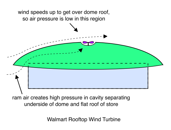
Walmart Rooftop Wind Turbine

Though not shown in the diagram above, slats are positioned in the gap between the edge of the flat top of the Walmart building (dotted line) and the bottom of the dome roof. (This is the gap through which the ram air flows in under the dome roof.) The slats can open and close to allow or block this flow. With the wind direction depicted above, all of the slats on the left hand side of the diagram would be open in order to allow the ram air to enter from the left and concentrate beneath the dome, and all of the slats on the right hand side would be closed to prevent its escape. The original post describing this idea, Venturi Dome Baseball Stadium, has a diagram that shows how the slats work. Another post, Rooftop Wind Turbine, described a rooftop turbine for a typical residence.

Idea #5) Another Walmart Rooftop Wind Turbine
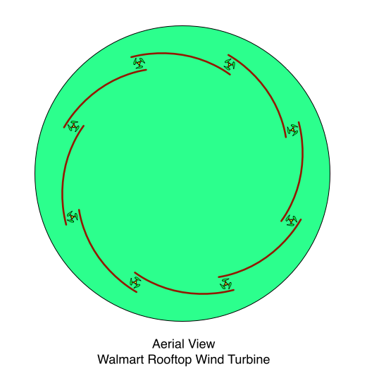
Aerial View Walmart Rooftop Wind Turbine

Simply put a Circular Wind Dam onto the roof of a Walmart store. In order to reduce turbulence, the store is first provided with a dome-shaped roof, and the Circular Wind Dam is mounted on top of the dome. The dome would look a little like the dome in the Walmart rooftop turbine described previously, but it would not have a hole and a turbine rotor in its center. Also, there would be no slats or gap between the edges of the flat top of the store and the underside of the dome.

Idea #6) VAWT Forest With OmniDirectional Flow Accelerators

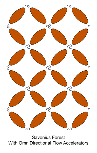
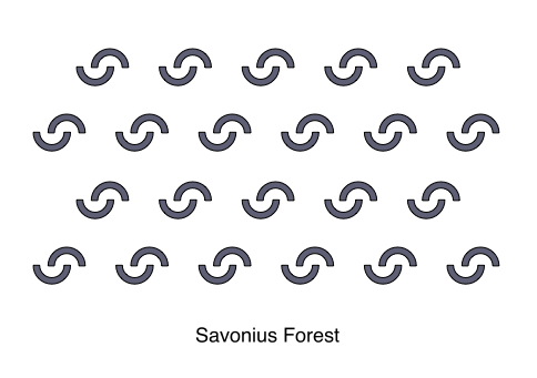
Savonius Forest With OmniDirectional Flow Accelerators

Here’s the original post: VAWT Forest With OmniDirectional Flow Accelerators.

Idea #7) Highly Scalable Horizontal Axis Wind Turbine

In the diagrams below, the orange and dark blue lines represent guy wires. Comments are provided that explain which load each guy wire supports.
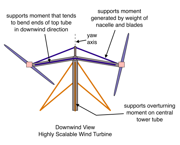
Downwind View, Highly Scalable Wind Turbine

Aerial View, Highly Scalable Wind TurbineThe Highly Scalable Horizontal Axis Wind Turbine is remarkable in that guy wires assist in supporting all of the large tower loads that are carried by the machine. This allows a great deal of weight and cost to be removed from the design. The original post explains in detail, and includes some very cool tilt-down versions.

Idea #8) Automatic Wind Turbine Blade Washer

Automatic Wind Turbine Blade Washer

If you don’t believe this embarrassingly simple device will work, then read the original post. You’ll be amazed that none of us ever thought of this idea until now.

Idea #9) Semi-Direct Drive Linear Turbine With Yawing Oblong Track

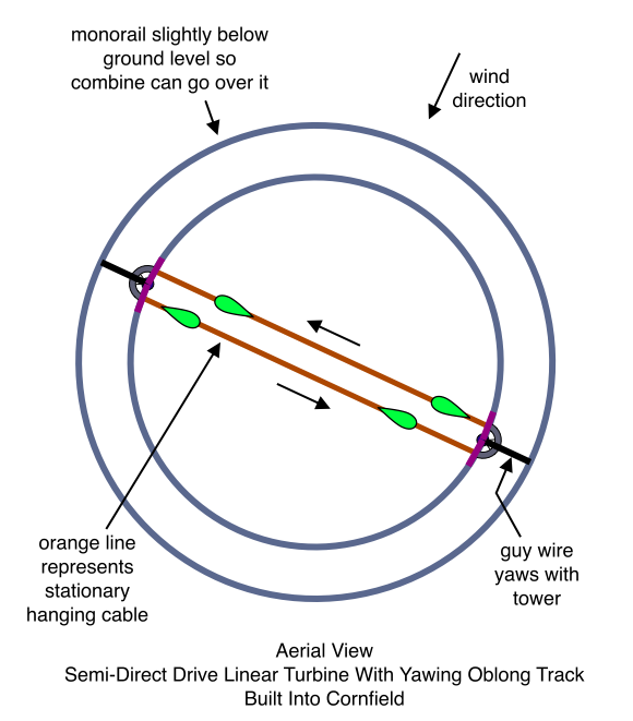
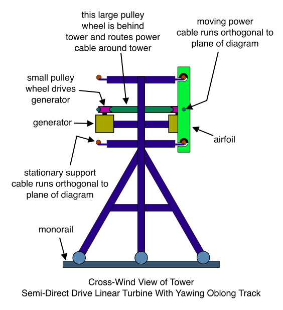
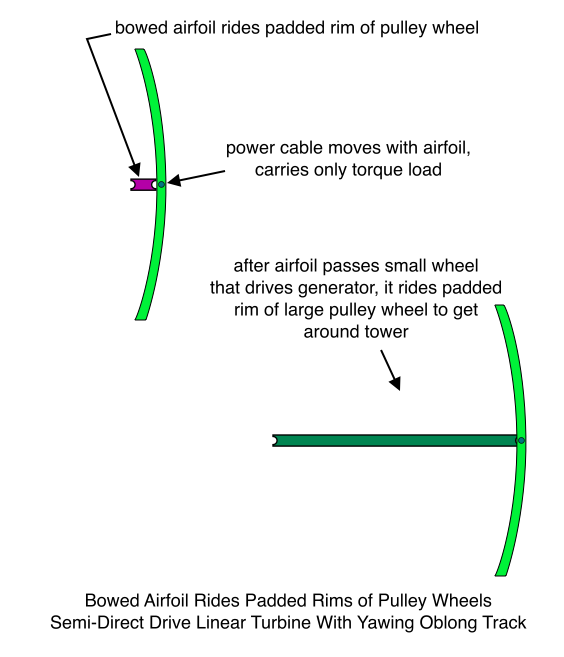
This one is too complicated to summarize, so I’ll just post a link to the original post that described it. But first, a word of advice – don’t be fooled by the apparent complexity of the diagrams. It isn’t as complicated as it first appears, and offers some tremendous performance advantages: Semi-Direct Drive Linear Turbine With Yawing Oblong Track.

More Good Ideas

Here’s a link to a page that is full of links to the best posts on the Salient White Elephant. That page has more links than are included the current post. Or if you’re really a glutton for punishment, you could just read every single one of the 127 Salient White Elephant posts!

Stationary Savonius Turbine

Stationary Savonius Turbine

Savonius in a Savonius

Since Savonius turbines are relatively impervious to turbulence, I wonder if the Stationary Savonius would make a good rooftop wind turbine? Can you imagine a giant Savonius in a Savonius on top of a Walmart store?

June 27, 2009

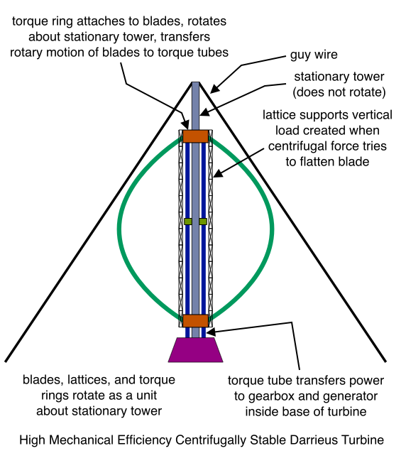
High Mechanical Efficiency Centrifugally Stable Darrieus Turbine

High Mechanical Efficiency Centrifugally Stable Darrieus Turbine

May 10, 2009

SkyScraper with H-Rotors

This is a very simple idea. Imagine a skyscraper that looks round in an aerial view. Now just put a bunch of disks around the outside walls of the building… (say) one disk every 6 stories or something like that. Now near the outer perimeters of these disks, you cut a slot as described in many of the other posts on this blog. (See for example 20 Megawatt VAWT.) The ends of the airfoils engage these slots. The blades go around the building with each level rotating with the same polarity as its upstairs and downstairs neighbors, or else with adjacent levels rotating with opposite polarity to double the speed difference between the generator rotor and the generator stator:

SkyScraper with H-Rotors

Mechanical energy may be converted into electrical energy in any of several ways. Once again, all of these conversion methods have been described multiple times on this blog, so I won’t repeat them here. I’ll just give a short list of the possibilities:

  • Generator windings are embedded into the slots. A permanent magent is attached to the ends of the blades and the motion of the blades forces these magnets past the windings.
  • Cables are attached to the middle of each rotor blade. These cables are attached to a smaller diameter cable. The diameter of the smaller diameter cable is just large enough to around the building without hitting it. The smaller cable drives the generator. All cables should be designed to carry only the power producing components of the airfoil loads. The larger (non-power producing) loads are carried by the disks that support the blades tips.
  • The slots that engage the blade tips are provided with a great many small wheels inside. Airfoil motion imparts spin to these wheels. All wheels are mechanically linked so that they all rotate at the same rpm. The rotational motion of the wheels (or of their mechanical linkage) drives a generator.

One question is whether blades that are rotating and producing power would be a visual distraction to the people inside the building. I honestly don’t know what the answer to this question would be. Because the building is high, and because the building itself acts as a flow accelerator, you can imagine that the blades might be traveling at a very high velocity indeed. I have no idea what the velocity would be, but let’s say they’re going 200+ miles per hour. Could you even see a blade moving at that speed? Anyway, if this turns out to be a problem, maybe one should explore the opposite approach – a great many blades having a slow, gentle movement.

Direct Drive Counter-Rotating Cat’s Eye Variation

In this variation, each level (each set of adjacent supporting disk-like structures) is provided with two sets of blades. Half rotate clockwise, and the other half rotate counterclockwise. (These blades may or may not be designed to imitate the behavior of the Cat’s Eye Darrieus Rotor.) The ends of all of the blades rotating with one polarity are attached to permanent magnets, while the ends of all the blades rotating with the other polarity are attached to windings. As two blades that rotate with opposite polarity pass by each other, their magnets and coils pass close to each other in a manner similar to what would be witnessed if you could look inside of an electric generator. The magnets and coils are attached to the parts of the ends of the airfoils that are hidden inside the slot, and thus create minimum drag and turbulence. The mechanical tolerances that must be maintained to minimize the air gap that the flux must traverse are acheivable also because these components live within the rigid and tightly controlled confines of the blade guiding slot.

April 28, 2009

High Speed Centrifugally Stable VAWT

(Note – there are some errors in this post that I haven’t had time to fix yet, but I’m sure that if you know mechanical engineering you can easily correct the errors yourself. I think this idea might have potential once the errors are corrected. Note also that the torque tube will probably remain fixed with respect to the stationary tower rather than rotating around it. Also note that the struts each need to be connected by a vertical lattice (near the stationary tower) to keep them separated… that is, to prevent the load that tends to bend the ends of the struts towards each other from being transferred to the rest of the structure, thereby defeating the fundamental purpose of the idea.)

(Okay, here’s a pic with some errors corrected, but with no explanation:

High Mechanical Efficiency Centrifugally Stable Darrieus Turbine

)

High Speed Centrifugally Stable VAWT, Side View

High Speed Centrifugally Stable VAWT, Aerial View

This is a 3 bladed turbine, but I have drawn only two blades in order to make the illustration easier to understand. And I realize there are a lot of “legitimate” mechanical designs to realize this concept, likely using gears instead of tires and so forth. But I’m not a mechanical engineer, and so I just want to draw something that will give the real designers an idea they can play with.

Because the tower does not rotate, the rotor can be very tall, very slender, and it can spin at high rpm without becoming centrifugally unstable. But can’t the stationary tower can bend just as much as the rotating tower? And if the stationary tower bends, won’t this cause the rotating part of the structure to become centrifugally unstable just as if the tower were rotating? No. To see this, consider what happens when the middle of a rotating tower bows in response to the lifting forces transmitted to the tower from the airfoil by the middle strut. In this case, the middle of the rotating tower bows in the downwind direction, but its rotational axis does not change. Therefore the mass of the rotating tower has been displaced from the rotational axis, and centrifugal force now acts to cause even more bowing, and the rotor has become unstable. But when the middle of the stationary tower bows in the downwind direction, the rotational axis of the middle struts and airfoils moves along with it. And so although the rotor’s axis of rotation is no longer straight, it is at least centrifugally stable.

Another advantage of this design is that the guy wires are not connected to the tower through bearings. This should provide a big reduction in mechanical losses, since the bearings at the top of a traditionally guyed Darrieus bear a very heavy load – the rotor’s overturning moment. Of course, the overturning moment must be supported somewhere by some bearings. This design has bearings inside the rings that the struts attach to. So is there any advantage in this compared to the traditionally guyed Darrieus? I’m not a mechanical engineer, so I don’t know. Maybe there’s no advantage at all, but I’m wondering if the approach here isn’t better because it is easier to influence the bearings at design time. For one thing, you can spread the load over as many bearings as you want, while the traditional design requires two sets of bearings – one at the top of the tower and one at the bottom. For another thing, the guy wires in the traditional design are not only trying to torque the bearings about a horizontal axis, they are also doing this cyclically, from very low torque to very high torque several times a second. Surely this can’t be good. Of course, the present design also places a cyclic load on the bearings – there’s no way to avoid that. But at least it’s a “typical” load in that it doesn’t try to twist the bearings to a new axis. So maybe this is a better approach. It seems to me that mechanical losses will be decreased by eliminating the torquing thing, but again, I don’t really have the background to know if this claim is accurate.

April 27, 2009

VAWT Forest With OmniDirectional Flow Accelerators

This post describes a field of stationary flow accelerators that I hope will be effective for any wind direction. Flow accelerators, or shrouds, are generally regarded as closer to science fiction than to a practical and economical idea. I think this may be due to the following problems:

  • It is difficult to yaw a large structure.
  • If the yaw system fails during high winds, the structure will fail.
  • The complexity and cost of the structure are probably greater than the complexity and cost of simply scaling up a more conventional and well understood design.

The VAWT Forest with OmniDirectional Flow Accelerators attempts to solve these problems as follows:

  • The flow accelerators are fixed. They do not yaw, and they rest on the ground.
  • The flow accelerators are equipped with vents that allow high winds to pass through the structures without generating much drag.
  • The cost and complexity is low. The flow accelerators are basically nothing more than oblong shaped brick walls.

The diagram shows Savonius rotors, but the design might work with other types of VAWT rotors. However, because of the relatively unpredictable and complex flow patterns that are likely to be created with this design, I am assuming that the Savonius might be a good choice, because it is mechanically and aerodynamically robust, and because it is relatively insensitive to turbulence:Savonius Forest With OmniDirectional Flow Accelerators

What’s so great about this idea? It seems incredible that you could develop a fixed flow accelerator that is equally (or almost equally) effective for every wind direction. The trick here, of course, is that only the accelerators that are in the interior of the forest are equally effective for every wind direction. The ones on the periphery of the forest may not accelerate flow at all for certain wind directions! But the design is effective because we can make the forest very very large – with many accelerators and many turbines. In this case, the number of turbines and accelerators that are at the periphery of the forest account for only a very small fraction of the total number turbines and accelerators.

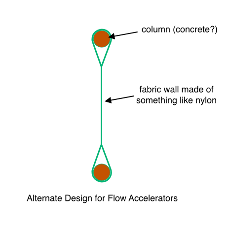
Here’s a simpler way to make the flow accelerators that might be less expensive and that still avoids making the wind flow around sharp corners:

Alternate Design for Flow Accelerators

I think this idea looks pretty good as is, but we can experiment further by putting circular shaped energy exchangers over the large empty places formed by the flow accelerators. These energy exchangers are able to rotate in order to align with wind direction. The slotted channels cause the oncoming (high energy) wind to flow down into the empty areas between the flow accelerators, and they also cause low energy air that has already flowed through the rotors to flow up and out of these empty areas in the downstream direction:

Counter-Sloping Energy Exchange Channels

Savonius Forest With OmniDirectional Flow Accelerators and Rotating Energy Exchangers

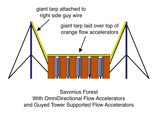
Another variation has a tarp lying across the roofs of all the flow accelerators, and places towers along the four edges of the Savonius Forest that support angled tarps. The following diagram omits the towers and the tarps that would be in the front and the rear of the view shown. (That is, only the towers and tarps on the right and left are shown – the ones in the front and back are omitted.)

Savonius Forest With OmniDirectional Flow Accelerators and Guyed Tower Supported Flow Accelerators

I am not an aerodynamicist, but I have always had the feeling that ducted rotors waste a lot of the accelerated flow created by the shroud. Wind tends to veer around obstructions. This is the reason for the Betz limit – the more energy you extract from the wind, the more you are slowing it down, the greater is the obstruction to flow, and the more the oncoming wind veers to avoid the obstruction. The idea proposed here is that more rotors should be placed in the path of the wind that is attempting to make its way around the turbines. Now I realize that this smacks of an “eternal motion” kind of logic. Isn’t it true that all of the turbines and all of the flow accelerators may be regarded as a single energy harvesting device, and that the Betz limit will apply to this large composite “turbine” just as well as to a single ducted rotor? Well… I’m not sure. The situation is complicated somewhat because the rotors are dispersed in the upwind and downwind directions as well as in the cross-wind directions. But let’s just suppose that the dispersed nature of this design is indeed subject to the same limitations as a single ducted turbine. Doesn’t it still enjoy the advantage of being omnidirectional? And isn’t it easier to design and build a number of small rotors instead of a single giant one? And isn’t it nice that the small rotors will spin at high rpm, thus reducing torque? And there is an aspect of the omnidirectional nature of this machine that I can’t quite wrap my mind around. It is as though the energy is filtered through the turbines like the way you might imagine rainwater making its way down to the aquafer. That is, if the pressure becomes unbalanced for some reason, the wind just might decide to flow in the crosswind direction. This seems possible since once inside the maze of flow accelerators, air has no “direct contact” with the wind outside the maze. (If this doesn’t sound very scientific, then you are obviously not a graduate, as I am, of the Billy Mays two week engineering correspondence course with complimentary “Senior Engineering Manager Your Name Here” wall plaque.)

There is another feature of this design that appeals to me as well. It seems to me that in the past, designers of ducted machines have assumed that a flow accelerator must be symmetrical. This seems like a critical mistake to me. One of the problems with flow accelerators is that they are huge, unweildy, expensive, and vulnerable to damage in storm winds. But the dispersed “Forest” idea shows that you aren’t constrained to expanding in symmetrical directions – you can simply ignore the vertical direction and spend your money expanding in the horizontal direction alone. Or, more likely, you can develop mathematical design techniques that can predict the optimal aspect ratio.

April 26, 2009

Flow Magnified VAWT Forest

Flow Magnified VAWT Forest

Segmented Circular Wind Dam With Adjustable Flow Accelerators

Segmented Circular Wind Dam With Adjustable Flow Accelerators

Almost all of the AeroArchitecture (non-turbine) part of this machine is fixed. The only part of the flow manipulating structure that is not fixed is the curved blue panels. The rotational angle of these panels is regulated by the turbine controller, and is a function of wind direction. I have drawn these panels at what I believe to be approximately the correct rotational angles given wind direction, but of course this is only an intuitive guess. I think some detailed aerodynamic modeling will be required to determine the optimum angles for the panels. However, let me explain the reasoning behind my guess.

Let’s begin by pretending that the adjustable panels and the turbines are not present, and that the circular wall does not have segments cut out of it. In other words, the wind is flowing around a very tall round wall. In this case the high pressure region will be around the most upwind part of the wall. The flow accelerates to get around the wall, and I think the lowest pressure will be approximately at the 3 o’clock and 9 o’clock positions. The flow about the rest of the wall is oscillatory and unstable. Vortices are shed in alternating fashion, first from one side of the wall and then from the other. For example, the flow may detach at about 4:30, and a clockwise vortex (with a vertical axis) will spin off of the wall at that point. Then the flow will detach at about 7:30, and a counter-clockwise vortex will spin off the wall at that point. Then the pattern will repeat. So the first thing to notice is that it may be desirable to add adjustable panels at 2:30, 4:30, 7:30, and 10:30 in order to prevent the vortex shedding. I have not drawn these panels because I don’t know if they will actually be necessary. Remember that the wind is being de-energized by the 4 turbines, and maybe this will be sufficient for stabilizing the flow. In any case, let’s forget about the vortex shedding for a moment, and consider the system as depicted above (with the segments removed from the wall, the curved adjustable blue panels, and the turbines present just as depicted in the diagram).

As I said, the high pressure occurs at the 12 o’clock position. As the diagram shows, the wind is flowing more or less straight at the 12 o’clock turbine. In this case, both the adjustable curved panels and the curved parts of the wall that extend downstream from the turbine act to concentrate and accelerate the flow through the 12 o’clock turbine.

Now let’s consider the 3 and 9 o’clock turbines. I am reasoning that the wind is moving slow and is at a relatively high pressure in the regions just inside the wall near these two turbines. This is true because the wind has been forced to flow through a very large cross-section inside the wall, and also because the wind has been de-energized somewhat as it passed through the 12 o’clock turbine. On the other hand, the velocity is at a maximum and the pressure at a minimum in the areas that are outside of the wall and outside of the 3 o’clock and 9 o’clock turbines. This is true because the wind has had to speed up to get around the wall, and also because it has yet to pass through any turbines, and so it hasn’t had energy extracted from it yet. Based on all this reasoning, I have elected to orient the adjustable panels so as to further encourage the flow that already wants to happen anyway – that is, the flow from slow high pressure inside the dam to fast low pressure outside the dam. When you consider what normally happens when wind flows through a turbine, you see that it is not exactly as I have described:

  • Flow through a traditional turbine is from high velocity and high pressure to low velocity and low pressure.
  • The flow that I just described is from low velocity and high pressure to high velocity and low pressure.

So maybe my reasoning is flawed. Of course, the rules will be changed when flow is manipulated, and in this case we are not only manipulating the flow, but we are manipulating it a great deal with a very very large structure. So I guess the only way to figure out whether my reasoning is correct is to build a sophisticated aerodynamic model and see what it says. Anyway… if you take a look at the hypothetical path of flow I’ve drawn near the left side of the diagram, you can see that the flow will be exiting the trailing edge of the adjustable panel at high velocity, just like the way air exits the trailing edge of an airplane wing. So I am reasoning that this flow will draw the dead air out of the inside of the dam and through the turbine.

Now for the 6 o’clock turbine. This one seems pretty straightforward. On the one hand, you might expect that the adjustable panels and the fixed curved parts of the wall that extend upwind of the 6 o’clock turbine should together look exactly like the flow accelerating structure around the 12 o’clock turbine. The reason I haven’t drawn it that way is because assuming we are able to successfully prevent the flow from detaching from the wall and spinning into a vortex, then the flow will be wanting to curve in the downstream direction as it continues its journey away from the wind dam in the downwind direction. In this case, the panels need to be rotated toward this path somewhat so that the flow doesn’t collide with the most downwind end of the adjustable panel and spin off of that sharp edge in a vortex.

April 25, 2009

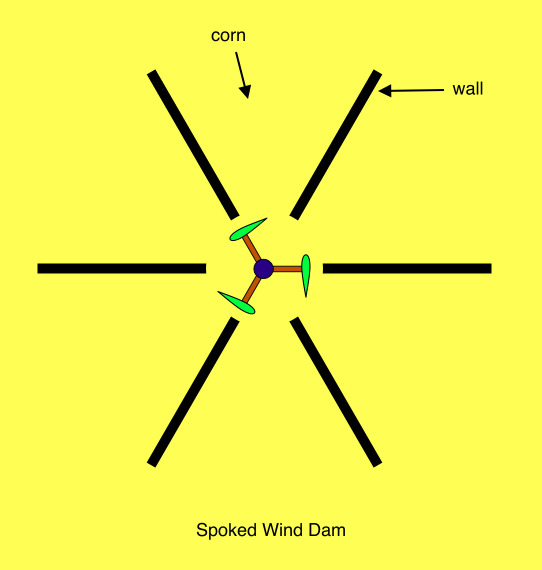
Spoked Wind Dam

This is an extremely simple idea. Walls are built that radiate like the spokes of a wheel, and a VAWT is placed at the “axis of the wheel”. That’s all there is to it!!!

Spoked Wind Dam

If desired, the lower edges of the walls may be raised up off the ground so that the walls do not impede the movement of the combine. In this case, pillars hold the walls up off the ground.

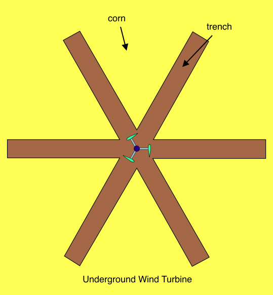
Underground Wind Turbine

The two diagrams below show aerial views of the underground wind turbine. The first diagram omits the doors that cover the trenches.

Underground Wind Turbine

The doors are visible in the following diagram. The doors may be opened so that either long edge may be raised, while the opposite long edge remains at ground level. Because the diagram isn’t three dimensional, it might be a little hard to comprehend at first. But it is easier to understand if you keep in mind that the width of the doors is exactly the same as the width of the trench that it covers below:

Underground Wind Turbine Showing How Doors Open to Capture Wind

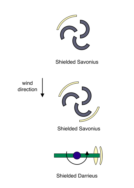
Shielded VAWT

This post proposes to increase the efficiency of a VAWT with yawing shields. In the case of the Darrieus, for example, the drag on the blade as it travels in the upwind direction is reduced by diverting the flow with a shield. The flow that is not diverted is slowed because the channel becomes wider in the middle. The flow on the opposite side of the rotor (left side in the diagram below) is not manipulated because it is already in the direction of blade velocity, and it therefore already reduces drag. As for the Savonius, I’m not sure if the idea will work, but I’ve drawn my best guess at how to augment the efficiency of the turbine using either one or two shields.

Shielded VAWT

April 23, 2009

Reciprocating Blimps

Two blimps are moored to each end of a horizontal tube or lattice structure that is near the ground. The tube rotates about a vertical axis that goes through the center of its longitudinal dimension. Each blimp is equipped with a giant light-weight parachute that looks like an old World War II parachute. These parachutes can be opened up to create a high drag profile, or closed to create an extremely low drag profile. When one blimp opens up its parachute, the other closes its parachute. The blimps take turns opening their parachutes in order for the wind to drag alternately drag each in the downwind direction. The reciprocating action of the horizontal mooring tube drives a generator.

Alternatively, perhaps a large “venetian blind” structure hangs from each blimp. The slats in these blinds can be opened up to create near zero drag profile, or closed to create a high drag profile. This variation is modeled after the turbine depicted below:

Here’s an embodiment that uses venetian blind like slats:

One of a Pair of Reciprocating Blimps

Rotary Variation

This is the same idea, except that the horizontal tube rotates instead of reciprocating. As the end of the tube begins its 180 degree “downwind sweep”, the blimp that is moored to it closes its slats to create maximum drag, and the other blimp opens its slats to minimize drag.

Adding HAWT Rotors

Instead of using drag devices, a giant HAWT rotor can be attached to the tail of the blimp. The rotor has very long, very light weight blades that rely on centrifugal stiffening to maintain their extended shape. These minimize drag by feathering their blades, and maximize drag by pitching their blades to a position similar to a HAWT turbine that is producing power. The drag action is similar to the lifting action of an autogyro. In other words, the HAWT rotors are not present to generate power directly. They are only present to control the drag profile of the blimp. On the other hand, perhaps a means can be devised for allowing them to augment the power produced by the system. In order to keep the weight of airborne components to a minimum, they do not produce very much electricity, but they do add a little bit to the electricity that is produced on the ground.

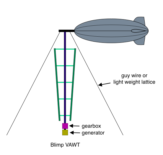
Blimp VAWT

Since no people will ride in the blimp, I guess it could be filled with hydrogen.

Blimp VAWT

I’m always drawing 2 bladed VAWTs when I really mean 3. A three bladed VAWT produces relatively constant power, and more importantly in this case, thrust. Since wind speed will normally increase with altitude, blade radius increases with altitude so as to maintain a more constant tip speed ratio. For simplicity, I drew only 2 guy wires. In reality, at least three would be required.

The turbine’s rotational axis can tilt, and the gearbox and generator tilt along with the rotor axis. This allows the wind turbine to seek its optimum orientation given wind speed and other parameters. Alternatively, perhaps the lower end of the wind turbine (the generator) is on wheels and is able to move if the turbine wants to move. Since the structure will be very heavy, the control system would likely control the movement of the generator this way and that along the ground as wind conditions change. But if we let the lower end of the turbine move, then we may as well save some weight by using only one guy wire or lattice to moor the blimp. In this case, the turbine will “yaw” by roughly tracing out a circle about the guy wire anchor point as the wind direction sweeps through a 360 degree arc.

The teardrop streamlined shape of the blimp is critical. If any old shape is used for the floatation device, then the wind will tend to carry it downstream. I don’t know what the optimum aerodynamic profile would be, but you would want to minimize drag. For this reason, perhaps a very elongated shape (kind of like a cigar) might be used.

Kites and Airfoils

Additional lift may be generated if a kite is positioned on top of the blimp. Imagine, for example, those modern parachutes that look like a big airfoil made out of something like nylon. If one of these is mounted on a vertical pole that extends upward from the blimp, then it will “take flight” when the wind speed reaches a sufficient value. In this case it will be available to add further support for the turbine whenever the turbine is running and producing power. Some kind of inflatable airfoil might do the same trick. If a kite or modern parachute is used, it will be suspended by its supporting structure in a shape and orientation that “prepares it” for taking flight when the wind picks up.

Other Variations

I think there must be many ways to develop better configurations if more than one blimp is employed. For example, two blimps could be moored to a giant circular railroad track. The anchor points are “yawed” so that a line connecting them forms a right angle with wind direction. The blimps are connected by a cable, and multiple VAWT turbines are suspended from the cable that connects the two blimps.

Weight is obviously one of the primary issues with airborne turbines. Perhaps some sort of inflatable airfoils can be used. The airfoils may even themselves be filled with hydrogen. Or a design similar to those light-weight modern parachutes might be used for the blades.

April 21, 2009

VAWT Forest

Many tall slender VAWT rotors are optimally dispersed and mechanically linked to drive a single generator.

Savonius Forest

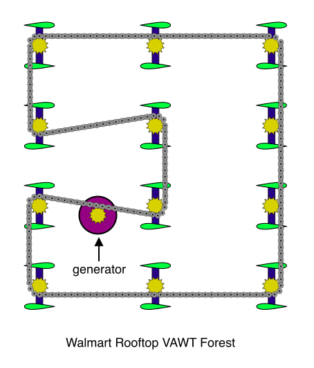
Walmart Rooftop VAWT Forest

A weather protection shroud (not shown above) runs along the same path as the chain and protects components from rain and other weather. It may also be desirable to explore the option of using a rotating drive shaft to transmit power from turbine to turbine, and finally to the generator. I won’t draw this option, because I’ve already drawn it for one of the variations below.

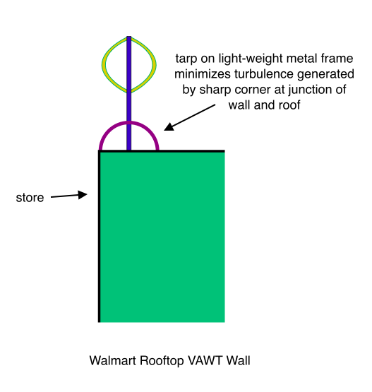
In the following embodiment, rotors form a wall along the four sides of the roof. A tarp that is supported by a lightweight metal frame runs along each of the four sides of the roof and beneath the rotors. The tarp minimizes turbulence.

Walmart Rooftop VAWT Wall

Variable Scale Deployment – Rotors Suspended From Tubes

This embodiment is suitable both for utility scale deployment, such as a large VAWT Forest suspended over a cornfield, as well as for small scale deployment, such as a rooftop turbine for a residence.

One Row of VAWT Forest Suspended From Tubes

In this variation, rotors are suspended from a bunch of tube segments. The tubes are connected by flexible joints that allow them to approximate the troposkein shape of a cable. Suspended VAWT rotors drive a chain that runs inside the tubes along their longitudinal dimension. A universal joint connects the turbine rotor shaft to a second shaft above the turbine rotor. The weight of the turbine rotor keeps its shaft approximately vertical. However, in high winds the lower end of the rotor shaft can swing in the downwind direction, thus regulating power output and thrust load on the supporting tubes. The yielding rotor shaft also provides a low drag profile storm wind shut down mechanism. The drive chain bears only a relatively low torque load, since tubes carry the gravity load, and since the diameter of the turbine rotor is relatively small (so that the rotor turns at relatively high rpm). Whatever the chain load, it acts to lift the row of turbines up against the force of gravity, and it also cancels some of the gravity load supported by the tubes. Only a single chain runs down one row of turbines because the return path for the chain is through the next higher level of turbines:

Path of Drive Chain, VAWT Rotors Suspended From Tubes

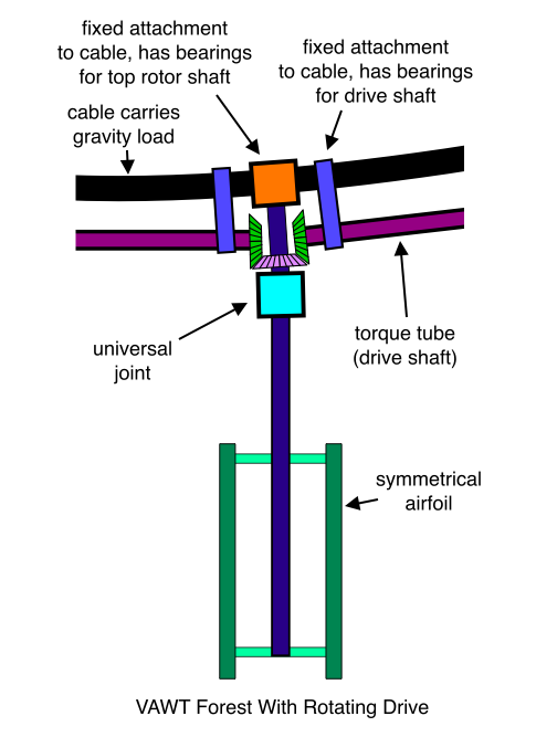
Rotors Suspended From Cables, Counter-Rotating Torque Tubes

VAWT Forest With Counter-Rotating Drive

VAWT Forest With Counter-Rotating Drive (Zoomed In View)

The universal joints not only allow for transferring mechanical power to a slightly different axis, they also permit the rotor to yield in response to wind gusts, and to assume a nearly horizontal orientation when the machine is shut down for storm winds. Note that if the wind direction is at a right angle to the cable, then the cable will twist in response to rotor thrust. This does not present a problem because the orientation of the torque tubes is fixed with respect to the cable, and so the torque tubes move along with the cable when it twists. The orientation of the top rotor shaft is also fixed with respect to the cable, so it rotates along with the torque tubes when the cable twists.

Reciprocating Drive

It is also possible to use a reciprocating drive for all of these machines. In this case, a tube is pushed and pulled by a crankshaft. Perhaps the simplest (and least expensive) option would have the crankshaft driving a cable. I will add some drawings of these options if I have more time later.

For more related discussion, see VAWT Wall.

VAWT Wall

A great number of very tall and very slender VAWT rotors are arranged into a circular wall. All rotors are mechanically linked to a common drive mechanism (chain and sprocket?) so that all drive a single generator:

Savonius Wall

Alternatively, the wall is separated into (say) 30 degree arc segments. All of the rotors that are contained in a given 30 degree arc are mechanically linked to drive a single generator, but each arc drives a separate generator. This way the arcs that are largely parallel to wind velocity will not drag down the arcs that are largely orthogonal to wind velocity. (And those arcs that are largely parallel to wind velocity may still produce a small amount of power.)

Of course, the same idea may be applied to any type of tall slender vertical axis wind turbine.

Suppose 2 bladed H rotors or 2 bladed Darrieus rotors are used. In this case the rotational angle of each rotor may be phase shifted somewhat with respect to its neighbors, and the power output of the machine will be very smooth.

Of course, it isn’t necessary for the wall to be circular in shape. I’m guessing that a circular wall would produce the most energy and the highest capacity factor at sites that have completely unpredictable wind directions. But if a site has a somewhat predictable wind direction, then the wall can definately be shaped to take advantage of the prevailing wind direction. Also, the wall may assume a non-circular shape in order to make its way around some obstruction like a barn or something like that.

Note also that the smaller the rotor diameter, the higher the rotor rpm! This characteristic might allow for eliminating the gearbox (or at least for reducing the speed change required, and thereby increasing the efficiency of mechanical power transmission.)

Seems like this machine may turn out to be suitable for almost any application you can think of – from small to gigantic utility scale wind turbines! Imagine a wall of these rotors on top of a Walmart. The rotors could be small diameter, fairly tall, and made of plastic. Even if a rotor flies apart it shouldn’t create a hazard since its only light weight plastic. And it certainly seems like this idea would be just absolutely perfect for low cost, clean energy in the third world! Imagine a machine like this driving the low-tech water transport pump I posted earlier:

Dirt Cheap Ultra-Simple Efficient Third World Water Transport Pump

Muti-Speed Transmission

Yawing VAWT Wall

This machine doesn’t need a yaw drive, as its yaw angle is self regulating:

Downwind Yawing Savonius Wall

Semi-Direct Drive Linear Turbine With Yawing Oblong Track

Ideal Path for Wind Turbine Blade

Doesn’t it seem like the ideal path for a wind turbine blade would have the entire blade moving at “tip speed”, spending the majority of its time traveling in a direction that is orthogonal to the direction of the wind?

Description of the Machine

Aerial View Semi-Direct Linear Turbine With Yawing Oblong Track Built Into Cornfield

(Note that the word “power cable” in the diagram below does not refer to an electrical cable, but rather to a cable that carries the mechanical power to the pulley wheels at the generators.)

Side View of Semi-Direct Drive Linear Turbine With Yawing Oblong Track

Looking at Leading Edge of Airfoil Semi-Direct Drive Linear Turbine With Yawing Oblong Track

Cross-Wind View of Tower Semi-Direct Drive Linear Turbine With Yawing Oblong Track

Bowed Airfoil Rides Padded Rims of Pulley Wheels Semi-Direct Drive Linear Turbine With Yawing Oblong Track

Aerial View of Apparatus That Routes Airfoil and Power Cable Round Tower Semi-Direct Drive Linear Turbine With Yawing Oblong Track

Drag on Moving Cable

How much aerodynamic drag does a moving cable add to the system compared to the drag of a strut or the low speed part of a troposkein Darrieus blade? Consider an H Rotor supported by a strut. The instantaneous velocity of a given radial location on the strut is at right angles to its longitudinal dimension. For this reason, it is able to leave a semi-evacuated space behind it as it moves. This space is filled with turbulent air. But the velocity of a given cylindrical cross-section of a cable is along its longitudinal dimension. Because there is always more cable following any cylindrical cross section, it is impossible for the cable to leave a semi-evacuated space in its wake. The only semi-evacuated, turbulated space it can leave is on its downwind side, and the force thus produced cannot drag down the system because it is orthogonal to the velocity of the cable. The only aerodynamic drag that is possible is that drag that is created by the cable’s ability to “stick to the air around it”. I’m not an aerodynamicist, but I’m guessing this might turn out to be pretty small. Also, the moving cable in the machine presented here has small diameter because it moves at “tip speed”, and because it is only required to carry the torque at tip speed. Because tip speed is high, torque will be low, and the cable will have small diameter.

Circular Variation

One obvious disadvantage of the oblong path is the need to yaw the track. We can eliminate this problem by providing the turbine with a polygonal path that approximates a circle:

Aerial View Showing Polygonal Path That Is Approximately Circular

Airfoils Could be Slowed to Go Around Tower

To avoid inflicting excessive centrifugal force on the blades as they go around the tower, maybe the control system could sense the point at which blades are nearing towers, and slow them down somewhat as they make their way around the tower. Alternatively, mechanical support could be provided on the opposite side of the airfoil to prevent excessive bowing due to centrifugal force:

Wheels Support Airfoil as it Rounds Tower

Low Drag Airfoil Variation

The airfoils need to have gaps near the regions where the load carrying cables penetrate them. This is necessary to accomodate the mechanical supports for the apparatus that steers the airfoils around the tower. But if the airfoils carry a small generator, like the generator that rubs against a bicycle tire in order to power a light for the bicycle, then these gaps could be filled with streamlined shapes during the long path between the two towers. The streamlined shapes would be pulled out of the way as the airfoil makes its way around a tower. The actuating mechanism is powered by electricity that is generated from the small generator just described that is located inside the blades.

Alternatively, maybe the streamlining shapes could be pushed out of the way by some mechanical means as the airfoil goes around a tower.

April 18, 2009

Pseudo-Lifting Fractal Turbine

When I first started learning about wind turbines, I wondered why a wind turbine with 2 or 3 blades was described as “aerodynamic”, or “highly efficient”.

Sleek, Highly Efficient, Modern HAWT
So much of the swept area seems unaffected by the blades. Surely adding more blades would allow for harvesting the energy in the wind that seems to be “escaping” through the large regions that are between the blades in the diagram above. This issue is discussed with the aid of the word “solidity”, which refers to the ratio of the area occupied by the blades divided by the total swept area. Surely the higher the solidity the better… no?

High solidity is a desirable feature with turbines that do not employ lifting surfaces. But a turbine that uses airfoils, like the one in the diagram above, is perfectly able to influence air “from a distance”. Imagine a long straight line of people dancing “the train”. Each has her hands on the shoulders of the person immediately before her. You’re standing there beside the line, and just as the last person goes by, you jump in line behind her. Then you put your hands on her shoulders and start dancing with the rest of the people in the train, but you kind of “drag your feet”. That is, you move more slowly than the rest of the train. Because the train is outrunning you, your arms will have to stretch out forward. And since you’re pulling back on the shoulders of the girl in front of you, she will have to slow down too. Her arms will have to stretch out forward, and so she slows down the guy in front of her, and so on. In this way, you cause the whole train to slow down, though you’ve only touched the girl immediately in front of you.

I think this is exactly how a lifting wind turbine manages to draw kinetic energy from air that has already “escaped” through the empty spaces between the blades:

Airfoil Exerting Influence From A DistanceYou may have heard that wind turbines with lifting devices are far more efficient than those that rely on drag forces alone. I can think of two ways of looking at this. First, the lifting force created by suction on the low pressure side of the airfoil is much larger than the lifting force created by ram air pressure on the other side. I read once that the suction force is 5 times greater than the ram air force. Second, most drag devices create turbulence. Why is this bad? Imagine the long line of air molecules “dancing the train” past the high-speed airfoil rotor. Their momentum is in the downstream direction, and their motion is very orderly. It’s hard for a molecule to make its way back toward the rotor because everybody is moving downstream. It’s kind of like trying to drive slow on a Los Angeles freeway when everybody else is barreling by at 90 mph. But turbulence is disordered motion. Imagine a crowd of people in a riot. Everybody’s running this way and that, banging into each other and so on. Now imagine the air molecules passing a turbine rotor in this chaotic fashion. Not only is it easier to make your way back to the rotor, but in fact somebody may bang into you and push you back toward the rotor. For this reason, the rotor cannot maintain low pressure on its downwind side. This eliminates the suction force that the rotor might otherwise generate, and therefore there is far less force to torque the rotor against the generator and generate electricity. Of course, we didn’t need to go through all this analysis to realize that the drag rotor turns less of the wind’s kinetic energy into electricity. All we had to do is consider all the chaotic energy in the “wind riot” that is left in the wake of the rotor. All of this chaotic energy is energy that was not converted into electricity, and it therefore represents an inefficiency in the system. We’d like to design a rotor that slows all of the air gently and evenly, leaving the least amount of disturbance in the wake.

Now let’s talk about thunder – what is it? When lightning pierces a region of air, it heats the air in the region tremendously. But lightning is only present for a very short time, and then it disappears. The air that was in the path of the lightning bolt is very hot, meaning it has expanded. But immediately after the lightning bolt is gone, this heat is dissipated into the surrounding air. Now the pressure of the air that was left in the wake of the lightning is very low because it is still expanded. So the surrounding air collapses into this evacuated space with a tremendous slap and a deafening roar. How does this relate to the issue of solidity and turbine rotors exerting influence from a distance? The fewer blades a turbine has, the lower the solidity. In order for a 2 bladed turbine to exert as much aerodynamic influence as a 3 bladed turbine, it must spin faster. But if it can exert influence from a distance, why does it need to spin faster? Because it can only exert influence from a limited distance. Unlike the human train, each molecule in the wind train exerts just a little less backward force on the molecule that is next in line downstream, until eventually molecules exert no backward force at all on their downstream neighbors. This makes sense. If turbines could draw kinetic energy from wind that is 100 miles downstream, we’d be powering entire nations with just a handful of wind turbines. A 2 bladed turbine spins faster than a 3 bladed machine so that the wind that passes through the “empty regions” between the rotor blades doesn’t have time to escape the region of aerodynamic influence before the rotor has extracted its energy. (Although not relevant to the Pseudo-Lifting Fractal Turbine, I may as well go ahead and explain why a turbine cannot extract all of the kinetic energy from the wind that passes through its rotor. If a rotor took all of the energy from the wind, then the wind would not be moving at all, and we’d be left with giant piles of air molecules lying around the turbine! The good news is that this renewable energy waste is not radioactive; the bad news is that we’d have to hire a bunch of truck drivers to haul it off to the official government renewable energy waste dump. If you want to learn more about this phenomenon, look up Betz’ law in Wikipedia.)

You would think the rotor characteristics just discussed would lead us to select a 2 bladed rotor design in order to cut the cost of one blade from the cost of the turbine. Unfortunately, things are not that simple. A 2 bladed turbine makes more noise than a 3 bladed turbine. This is because a high speed 2 bladed rotor blade pierces the wind like a lightning bolt. Yes, the evacuated region on the downwind side of the airfoil is able to draw kinetic energy from wind that is already considerably downstream of the rotor, but the evacuated region that realizes this action subsequently collapses just like the collapsing air in the wake of a lightning bolt. The first large wind turbine I ever worked on was the 2 bladed Carter 300 kW machine. One fascinating aspect of this machine was that it was able to extract energy from wind traveling as fast as 40 miles per hour! Standing beneath this turbine in a 40 mph wind was like standing beneath a heavy military helicopter – VOP!!!… VOP!!!… VOP!!!… VOP!!!… VOP!!!… Although it belonged to the “featherweight class” of turbines, it produced the electricity of an expensive heavyweight champion. But a machine like this pays the penalty of noise. Such a turbine can’t be sited near places that have people – residential areas and so forth. And its high-speed airfoils are difficult for birds to see, so this further limits siting options.

Now that modern wind turbines have reached a scale of several megawatts, you can imagine the difficulty of designing a robust blade that’s 40 yards long. A wind gust hits a region of one blade at a point (say) 75% down its longitudinal dimension (near the blade tip), and not only must the 40 yard long slender blade dissipate the huge lifting force generated by this gust, but in fact that mechanical shock ripples throughout the entire slender turbine structure. It’s a little like trying to design a giant “stick man” using nothing but drinking straws, and requiring that he cannot be knocked down by even 100 mile per hour storm winds.

The Pseudo-Lifting Fractal Turbine

The Pseudo-Lifting Fractal Turbine proposes to solve many of these issues. It moves very slowly, and I think it should be extremely quiet. It won’t kill birds. It poses little danger in the case of an accident. (I can’t think of a way for this turbine to “run away” and fly apart like an unloaded traditional rotor.) It can’t impress an admiring green public with lightning flash signs of power, but it will just absolutely dazzle mechanical engineers with the simplicity of its scalable mechanical design characteristics. I am hypothesizing that this turbine delivers the efficient aerodynamic performance of a high-speed modern rotor, but with the low velocity of a drag rotor. I’ve prefaced its description with a long theoretical discussion because I developed this machine from that theory.

The turbine design begins by finding the “perfect” drag shape:

The Perfect Drag Shape

Now we fractalize this shape one iteration:

Fractalized Drag Shape
Now we approximate the small arcs with clamshell airfoils that can open up into the fractal shape, and that can close up into a shape that has a low drag profile:

Clammified Airfoils Approximate Ideal Drag Profile
(I’ve drawn the clamshells packed together like sardines. Not sure why I did this. If the rotor truly generates aerodynamic suction, then the long arguments presented earlier would seem to indicate that it isn’t desirable to have 100% solidity. But while thinking about this topic, I want to point out something interesting about the open clamshells above. Doesn’t it look like the ram air pressure would be higher than it would be were it only hitting a single angled airfoil!? And I wonder if the low pressure might also be augmented somewhat, since low pressure air can’t reach the high pressure side of the airfoil by zipping around its trailing edge.)

Now we use two clamshell airfoil fractals to make a reciprocating rotor. (The following diagram is zoomed out to the extent that you can’t see the smaller arcs… only the large ones.)

Pseudo-Lifting Fractal Turbine
When the clamshells on one side close, the clamshells on the other side open, and vice versa. I am hypothesizing that if this rotor is carefully designed to avoid the generation of turbulence, and if the rate at which the clamshell airfoils open and close is just right, then this turbine should use aerodynamic suction to siphon kinetic energy from the wind in a manner that is very similar to the action of a high-speed modern turbine rotor.

How is the machine yawed? Both the tower and the tube at the top of the tower reciprocate as the machine produces power. (The ring and the generator are at ground level.) But the tower-top tube is also able to rotate with respect to the tower. Its motion is fixed to the motion of the tower whenever a brake that connects the two is activated. When the controller detects a change in wind direction, it simply releases this brake at the appropriate time and for the appropriate duration to cause the tower-top tube to rotate with respect to the tower to the correct yaw angle.

The turbine is shut down during high winds by closing all clamshells and releasing the brake that controls the yawing action.

Variations

I guess there are a lot of variations on the ideas presented here. Here’s an example:

Reciprocating Savonius-Like Turbine

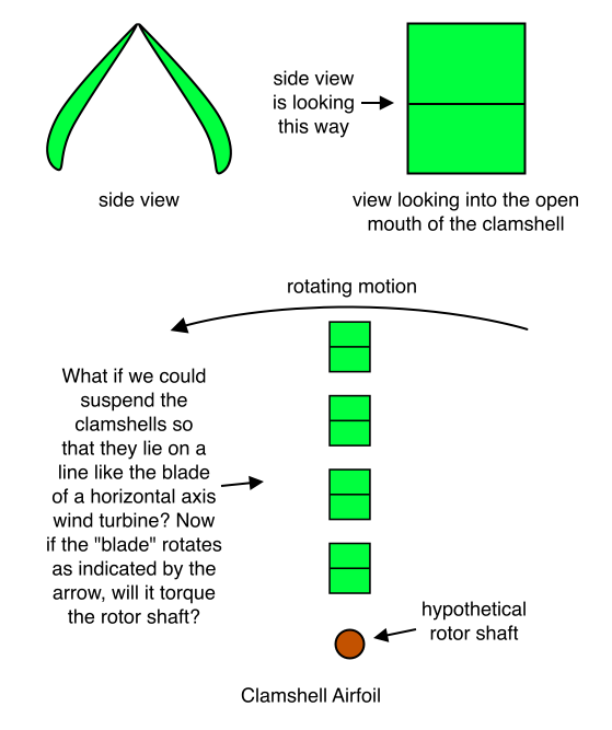
Earlier I asked whether the high pressure and low pressure might be augmented by the open clamshell airfoil shape. Here’s a diagram that examines this issue in different way:

Clamshell Airfoil

And if this works, then why not something along the lines of the following?

Staggered Clamshell Airfoil

Maybe if the staggered clamshell airfoil produces lift, then maybe it would additionally provide the advantage of mixing air of different energy levels. If so, it might eliminate the “dead air” that is present with some airfoil designs. Another interesting question is what kind of vortex activity might be generated by this device? On the one hand, I can see how it might make zillions of vortices, but on the other hand I wonder if they would mostly cancel each other?

I wonder if anybody has ever tried to think of ways to use fractal shapes to make a wind turbine. Seems like there might be some amazing new possibilities there doesn’t it?

April 17, 2009

Lifting Savonius

Lifting Savonius

April 15, 2009

20 Megawatt VAWT

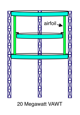
This is a 3 or 6 bladed machine, but I’ve drawn only 2 blades (and 2 towers) in the diagrams to make them easier to understand.

20 Megawatt VAWT

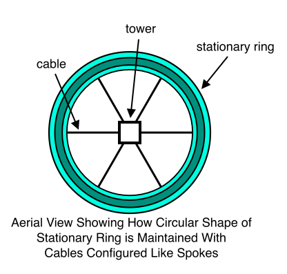
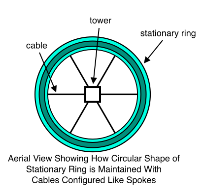
Aerial View Showing How Circular Shape of Stationary Ring is Maintained With Cables Configured Like Spokes

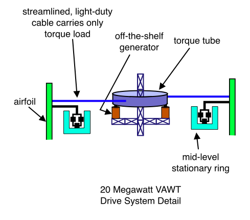
20 Megawatt VAWT Drive System Detail

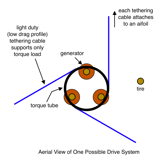
Aerial View of One Possible Drive System

The 20 Megawatt VAWT Exceeds the Betz Limit

The rule of thumb for separating horizontal axis turbines is that two turbines should not be closer than two or three rotor diameters. Apparently, after the streamtube has traveled two or three rotor diameters beyond the turbine, it will have re-absorbed kinetic energy from the surrounding wind to the extent that its energy density will have roughly returned to its original value. It’s easy to see how this will apply to a very large diameter VAWT. Simply imagine a ridiculously large turbine. Say for example the diameter of the VAWT described here is equal to the diameter of New York City. In this case it is obvious that the wind that passes through the downstream 180 degree arc will have just as much energy as the wind that passes through the upstream 180 degree arc. From this example we can see that the maximum fraction of energy that a very large diameter VAWT may extract is 2 x 60% = 120%. Darrieus rotors have a reputation for delivering lower efficiency than their horizontal axis cousins. However, given the doubling of the ceiling on energy extraction, it is reasonable to believe that a very large diameter VAWT may prove to be quite efficient. This is wonderful news, since one frequently cited reason for the gradual disappearance of the Darrieus from the windfarm landscape is that it has the larger weight per power ratio. The extraordinary scalability of the VAWT described here together with its ability to exceed the Betz limit may very well reverse this state of affairs.

Though I believe that a very large machine is possible with the configuration presented here, the design may also be useful for smaller machines. In this case, it seems like the outside towers might be eliminated:

Less Than 20 Megawatt VAWT

Another Variation

20 Megawatt VAWT

Aerial View Showing How Circular Shape of Stationary Ring is Maintained With Cables Configured Like Spokes

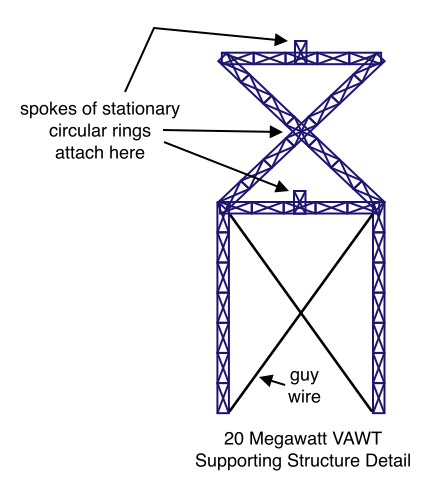
20 Megawatt VAWT Supporting Structure Detail

20 Megawatt VAWT Drive System Detail

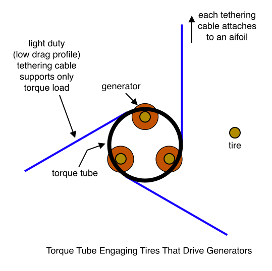
Torque Tube Engaging Tires That Drive Generators

Another Variation

20 Megawatt VAWT (Zoomed Out) (Legend)

20 Megawatt VAWT (Zoomed Out)

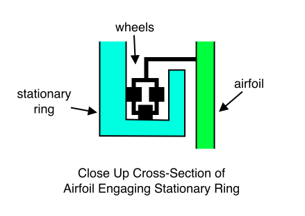
Close Up Cross-Section of Airfoil Engaging Stationary Ring

Aerial View Showing How Circular Shape of Stationary Ring is Maintained With Cables Configured Like Spokes

In the interest of clarity, the diagram has a number of simplifications. For example, at least three towers are required, but more than three towers may be used if needed. Why would you need more than three towers? Because the diameter of this machine can be made very very large.

Aerial View of One Possible Drive System

One design alternative would have the generators on the ground. In this case, the central tower is replaced by the torque tube, and the torque tube extends to the ground where it engages the tire that drives the generator. Another alternative would replace the cables in the drive system with symmetrical airfoils. Why use airfoils instead of tubes? To minimize drag. Why airfoils instead of cables? Look again at the diagram that shows the whole machine:

20 Megawatt VAWT (Zoomed Out)

If the (vertical) airfoils are tall, the cable might make them bow too much or might put too much vertical load on the rings. Using a streamlined airfoil to transfer torque to the torque tube would eliminate these problems.

Single Airfoil Support Variation

20 Megawatt VAWT (Blade Supported in Middle, Zoomed Out)

20 Megawatt VAWT (Blade Supported in Middle, Drive Mechanism)

20 Megawatt VAWT (Blade Supported in Middle, Drive Mechanism with Symmetrical Airfoil Strut)

This post shows improvements on ideas from earlier posts. I won’t duplicate earlier discussions here, but I’ve pasted links below in case you want to read more. One very important point that is explained in earlier posts is that the wind machine proposed here can exceed the Betz limit. In fact, this machine can extract 120% of the kinetic energy flowing through the swept area instead of just 60%.

April 13, 2009

High Altitude Guyless Darrieus

High Altitude Guyless Darrieus
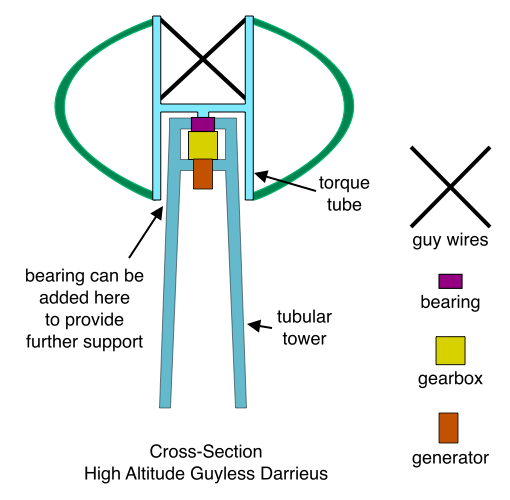
The key to this idea is that the torque tube encircles the top of a tubular tower (like you’d expect to find on a modern multi-megawatt horizontal axis wind turbine). Aerodynamic forces are approximately balanced with respect to the middle of the torque tube (that is, halfway down its longitudinal dimension). And the middle of the torque tube is the part that engages the bearing at the top of the tower. So aerodynamic forces inflict only a small overturning moment on the torque tube, and this overturning moment can easily be carried by some kind of wheel or bearing at the bottom of the torque tube that also engages the outside of the tower. The gearbox and generator are situated at the top of the tower just like they would be in a horizontal axis machine. Alternatively, the center part of the torque tube (barely visible in the above diagram) can extend all the way down to ground level where it connects to the gearbox and generator, all of which live in the comfortable surroundings of the inside the bottom of the tower.

I favor three bladed VAWTs, but I usually just draw two blades because it makes the diagram easier to understand.

The rule of thumb for siting horizontal axis wind turbines is that turbines should not be closer than two or three rotor diameters. I assume this means that by the time the streamtube has traveled two or three rotor diameters past the rotor disk, it has been re-energized by the surrounding wind. For this reason, I keep wondering what would happen if the diameter of a Darrieus rotor were three times larger than its height. Wouldn’t this mean that the maximum amount of energy that the machine could extract from the wind would be not 60%, but 120%? (60% for the upwind arc plus 60% for the downwind arc.) If so, wouldn’t this mean that the efficiency of a large diameter Darrieus might rival or even surpass the efficiency of a horizontal axis machine? In this case, we can build very robust arms that extend from the torque tube, two arms for each blade, and make the diameter very large. The parts of the arms near the axis of rotation can be large, very stiff, and very robust because the velocity is low near the hub, so we don’t need to worry about the arms generating too much drag.

Older Posts »

Blog at WordPress.com.